Alarm router optimizing strategy in target alarm system

An alarm system and target technology, applied in transmission systems, digital transmission systems, alarms, etc., can solve problems such as uncertainty in the transmission of alarm messages, and achieve the effect of reducing transmission failures and delays

Active Publication Date: 2016-06-15
DRAGERWERK AG
View PDF5 Cites 1 Cited by
  • Summary
  • Abstract
  • Description
  • Claims
  • Application Information

AI Technical Summary

Problems solved by technology

These different possible conditions can create uncertainty in the delivery of alert messages

Method used


Image

  • Alarm router optimizing strategy in target alarm system
  • Alarm router optimizing strategy in target alarm system
  • Alarm router optimizing strategy in target alarm system

Examples


Embodiment Construction

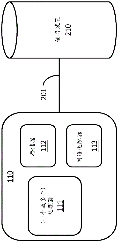
[0037] figure 1 is a schematic diagram of an example of an environment for implementing alert routing monitoring and optimization. Here, the targeted medical alert system 110 is in data communication with the end devices 131 , 132 and 133 via one or more of the cellular networks 161 , 162 , 163 and the WiFi network 151 . The terminal devices are each associated with a respective caregiver caring for one or more patients in the rooms / beds 142-149. The caregiver associated with terminal device 131 takes care of the patient in room / bed 142 , while the caregiver associated with terminal device 132 takes care of the patient in room / bed 147 . The caregiver associated with the terminal device 133 is at the caregiver central station 121, which may be provided with an alarm display system (eg connected to a local computer network by a hardwired data connection like Ethernet). Another alarm display system 171 is also provided in the common area (eg, in the foyer). The alarm display s...


PUM


Abstract

Described is a target alarm system which comprises a network detector which sends test data to terminal devices connected to a network and receives reliable data from the network. When target alarm information has to be sent, the system identifies a target terminal based on the reliable data so as to send the target alarm information. The invention also discloses related method, apparatus and non-provisional computer-readable media.

Description

technical field [0001] The subject matter described herein relates to alert routing monitoring and optimization strategies in targeted medical alert systems. Background technique [0002] In a distributed target alert system, there is a risk of failure or delay in the delivery of alert messages that could be harmful to the patient. Delivery failures or delays may occur at the system integration level. Even if the monitoring hardware and software alone were perfect, the timely delivery of alert messages would depend (at least in part) on eg a hospital's network infrastructure. Another factor that may cause delivery failure or delay is the terminal device (eg, iPhone, Android phone, pager) carried by the caregiver who will receive the alert message. Different network devices and even caregivers may have different reliability characteristics. For example, a central station hardwired via Ethernet will likely have a very reliable network connection, while a mobile wireless dev...

Claims


Application Information

Patent Timeline
Patent Type & Authority Applications(China)
IPC IPC(8): H04L29/08H04L12/26G06Q50/22H04W4/90
CPCG06Q50/22H04L43/08H04L43/0852H04L67/12A61B5/1113G06Q10/1091G08B25/001G08B26/006G08B26/007H04M2242/04G08B25/003G08B25/004G08B29/185H04W4/023A61B5/746G16H40/63G16H40/20H04W4/90G16H40/60
Inventor C.J.布劳斯
Owner DRAGERWERK AG
Why Eureka
Try Eureka