Waste gas purification device for pharmacy and chemical industries

An exhaust gas purification device and purification device technology, which is applied in the direction of combined devices, chemical instruments and methods, and the separation of dispersed particles, can solve the problems of slowing down the air flow in the air duct, unable to clean the gas, and blocking the activated carbon network, etc., to increase the contact time , Prevent safety production accidents, reduce waste of resources

Active Publication Date: 2016-06-22
NINGXIA SOFTWARE ENG INST CO LTD
View PDF4 Cites 9 Cited by
  • Summary
  • Abstract
  • Description
  • Claims
  • Application Information

AI Technical Summary

Problems solved by technology

In order to reduce the impact of factory waste gas on the environment, existing industrial plants are generally equipped with air purification devices, the purpose of which is to reduce the content of harmful substances in the air, so that the air discharged from the plant will not pollute the surrounding environment. The current industrial Air purification devices are mainly divided into two types: spray type and adsorption type. However, the spray type mainly increases and precipitates the particles and dust in the air, and cannot clean the gas thoroughly, and the water flow generated during spraying will decrease. The flow of air in the slow air channel and the adsorption type will cause the exhaust gas with larger particles and more debris to block the mesh of the activated carbon net and photocatalyst net, and it often has electrical components. When the humidity of the exhaust gas is high, the electrical components will appear. Damaged by short circuit, affecting its service life

Method used


Image

  • Waste gas purification device for pharmacy and chemical industries

Examples


Embodiment Construction

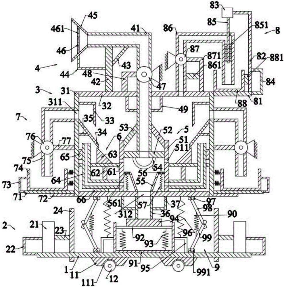
[0008] Such as figure 1 As shown, the pharmaceutical and chemical industry exhaust gas purification device of the present invention includes a bottom plate 1, a pusher 2 positioned on the left and right sides above the bottom plate 1, a purification device 3 positioned above the pusher 2, and a pusher positioned above the purification device 3. The air intake device 4, the concentration device 5 positioned below the air intake device 4, the first air outlet device 6 located in the purification device 3, the water inlet device 7 located on the left and right sides of the purification device 3, the The second air outlet device 8 above the purification device 3 and the recovery device 9 above the bottom plate 1 .

[0009] Such as figure 1 As shown, the bottom plate 1 is in the shape of a cuboid, and the bottom plate 1 is placed horizontally. The bottom plate 1 is provided with a first support block 11 below it and a first roller 12 below the first support block 11 . The first s...


PUM


Abstract

A waste gas purification device for pharmacy and chemical industries comprises a bottom plate, pushing devices, a purification device, a gas inlet device, a concentration device, first gas outlet devices, water inlet devices, a second gas outlet device and a recovery device, wherein first supporting blocks and first rollers are arranged on the bottom plate; each pushing device comprises a first air cylinder, a first support, a first pushing rod and a first pushing plate; the purification device comprises a purification tank, a first transverse plate, a first retaining frame, a first concentration plate, first cross rods, a first pipeline and first fixing frames; the gas inlet device comprises a gas inlet pipe, a first supporting rod, a first oblique rod, a second support, a gas inlet hopper, a first partition board, a first fan, a third support and fourth supports; the concentration device comprises a concentration frame, a second transverse plate, second oblique rods, a first filtering frame, a first concentration hopper and a first sealing ring; each first gas outlet device comprises a second partition board and a first connection rod. The waste gas purification device can completely purify waste gas in workshops of the pharmacy and chemical industries and clear dust and other impurities in the workshops.

Description

technical field [0001] The invention relates to the technical field of waste gas treatment, in particular to a waste gas purification device for pharmaceutical and chemical industries. Background technique [0002] With the gradual improvement of the degree of industrialization in our country, the waste materials discharged by factories in daily production are increasing day by day, so the pollution to the surrounding environment is becoming more and more serious. Among the emissions from factories, exhaust gas is one of the main sources of pollution, especially in enterprises such as cement factories, foundries, pharmaceutical factories, chemical plants or feed factories, where the exhaust gas contains a large amount of particles, dust or heavy metals. In order to reduce the impact of factory waste gas on the environment, existing industrial plants are generally equipped with air purification devices, the purpose of which is to reduce the content of harmful substances in th...

Claims


Application Information

Patent Timeline
Patent Type & Authority Applications(China)
IPC IPC(8): B01D50/00B01D53/78B01D53/50
CPCB01D53/507B01D50/60
Inventor 刘湘静
Owner NINGXIA SOFTWARE ENG INST CO LTD
Why Eureka
Try Eureka