

Disc type turbine agitator for reaction vessel
A turbine agitator and disc type technology, applied in the field of reaction kettles, can solve the problems of uneven mixing, uneven stirring, single stirring direction, etc., and achieve the effects of high stirring efficiency, uniform mixing and low energy consumption.
Inactive Publication Date: 2016-06-22
NANJING ZHONGTENG CHEM
View PDF0 Cites 0 Cited by
- Summary
- Abstract
- Description
- Claims
- Application Information
AI Technical Summary
Problems solved by technology
However, the energy consumption of ordinary agitators is large, and the agitation is easy to cause inhomogeneity. For the reactants in the liquid phase, it is easy to mix unevenly, agglomerate, and the agitation direction is single, which cannot form an effective liquid flow direction.
Method used
View moreImage
Smart ImageViewing Examples

Examples
Embodiment
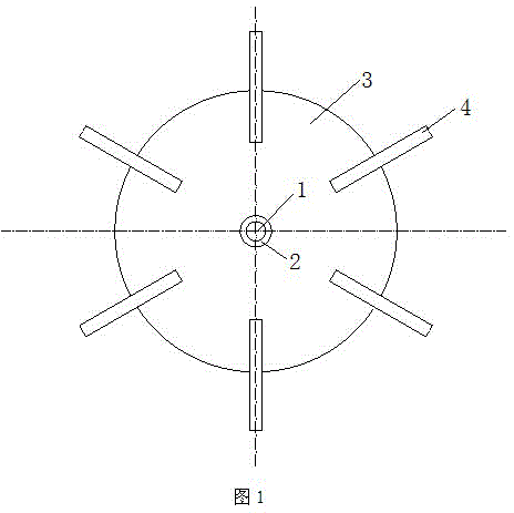
[0012] Example: A disc turbine agitator for reactors such as figure 1 As shown, it includes a shaft 1, a shaft sleeve 2, a disc 3 and six paddles 4, the diameter of the disc 3 is 350 mm, the shaft 1 passes through the center of the disc 3 and is fixed by the shaft sleeve 2, and the six paddles 4 are 60° is evenly welded to the circle of the disc 3, and the paddle 4 is bent in a wave shape; the curved paddle 4 can drive the entire reactor to form a wide and stable swirling flow at a relatively low speed.
[0013] The direction of the swirling flow formed in the reactor of this embodiment is clockwise at the upper part of the paddle 4, and counterclockwise at the lower part of the paddle 4.
Login to View More PUM
| Property | Measurement | Unit |
|---|---|---|
| Diameter | aaaaa | aaaaa |
Abstract
The invention discloses a disc type turbine agitator for a reaction vessel. The disc type turbine agitator comprises a shaft, a shaft sleeve, a disc and a group of blades, wherein the shaft passes through the center of the disc and is fixed through shaft sleeve, and the group of blades are uniformly distributed along the circumference of the disc and are bent. The disc type turbine agitator is low in energy consumption and high in agitation efficiency; liquid flow direction formed by agitation pervades the whole reaction vessel, so stable and agitated eddy flow is formed; thus, the disc type turbine agitator is applicable to emulsion, fluid suspension, etc.
Description
technical field [0001] The invention relates to a reaction kettle, in particular to a stirrer. Background technique [0002] In the reaction kettle, in order to speed up the reaction speed, strengthen the mixing and enhance the effect of mass transfer or heat transfer, etc., it is generally equipped with a stirring device. It consists of a stirrer and a stirring shaft, which are integrated with a transmission device by a coupling. There are many forms of agitator, which need to be selected according to the process requirements. However, ordinary stirrers consume a lot of energy, and the stirring is easy to cause inhomogeneity. For the reactants in the liquid phase, it is easy to mix unevenly and agglomerate, and the stirring direction is single, which cannot form an effective liquid flow direction. Contents of the invention [0003] Purpose of the invention: the purpose of the present invention is to overcome the deficiencies in the prior art and provide a disc-type turb...
Claims
Login to View More Application Information
Patent Timeline
 IPC IPC(8): B01J19/18B01F15/00
Inventor钟华陆敏山谢萍
OwnerNANJING ZHONGTENG CHEM