An integral cross wedge rolling mill driven by a hydraulic motor

A technology of hydraulic motor and cross wedge rolling mill, applied in the direction of metal rolling stand, metal rolling mill stand, driving device for metal rolling mill, etc. problems, to achieve the effect of improving space utilization, reducing occupied space, and moving evenly and stably

Active Publication Date: 2017-11-24
NINGBO UNIV
View PDF7 Cites 0 Cited by
  • Summary
  • Abstract
  • Description
  • Claims
  • Application Information

AI Technical Summary

Problems solved by technology

However, the existing cross-wedge rolling mills basically transmit power and torque to the upper and lower rolls through mechanical transmission mechanisms such as motors and gearboxes. It is difficult to achieve speed adjustment for different rolling requirements without adding gearboxes; And because the rolling process of cross wedge rolling belongs to the plastic deformation of metal, the required rolling force is relatively large, and there is a certain circular run-out error requirement during rolling. It is difficult for the current mechanical transmission mechanism to ensure that the roll Uniformity and stability of movement
In addition, most of the current cross wedge rolling mills are of split type, that is, the rolling mechanism and the transmission mechanism are arranged separately and connected by universal couplings, which occupy a large area, have low space utilization, and are also subject to certain restrictions in use.

Method used


Image

  • An integral cross wedge rolling mill driven by a hydraulic motor
  • An integral cross wedge rolling mill driven by a hydraulic motor
  • An integral cross wedge rolling mill driven by a hydraulic motor

Examples


Embodiment Construction

[0016] The present invention will be further described in detail below in conjunction with the accompanying drawings and embodiments.

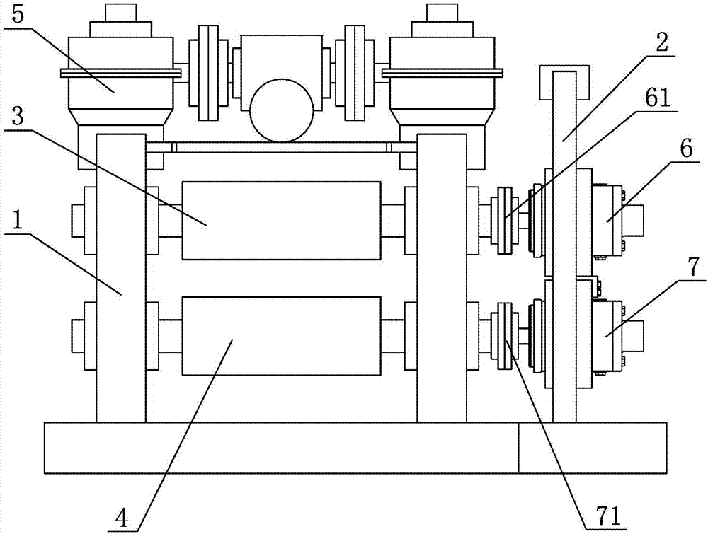
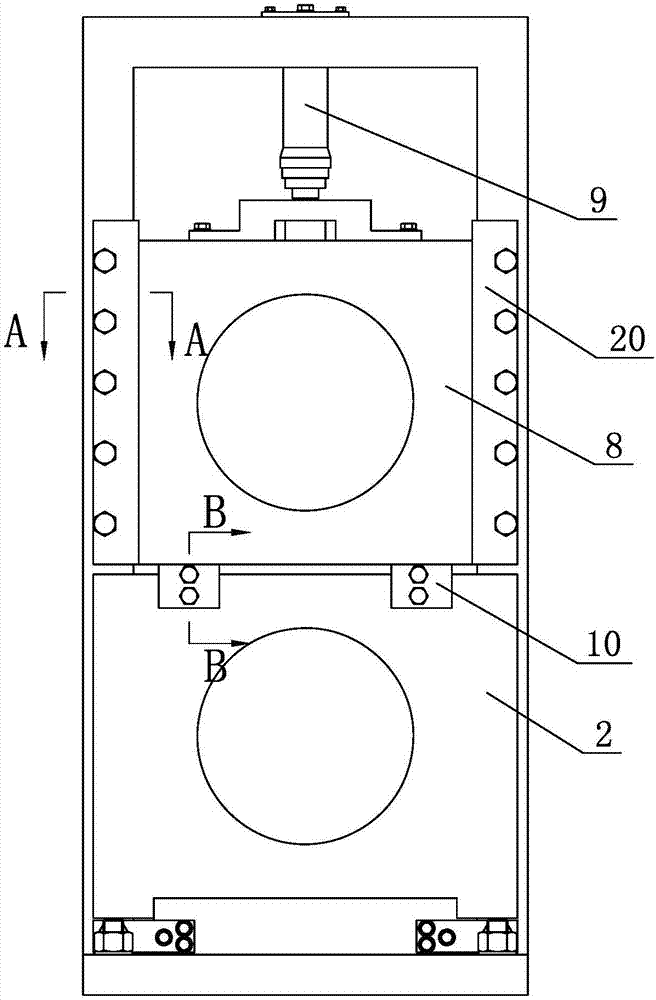
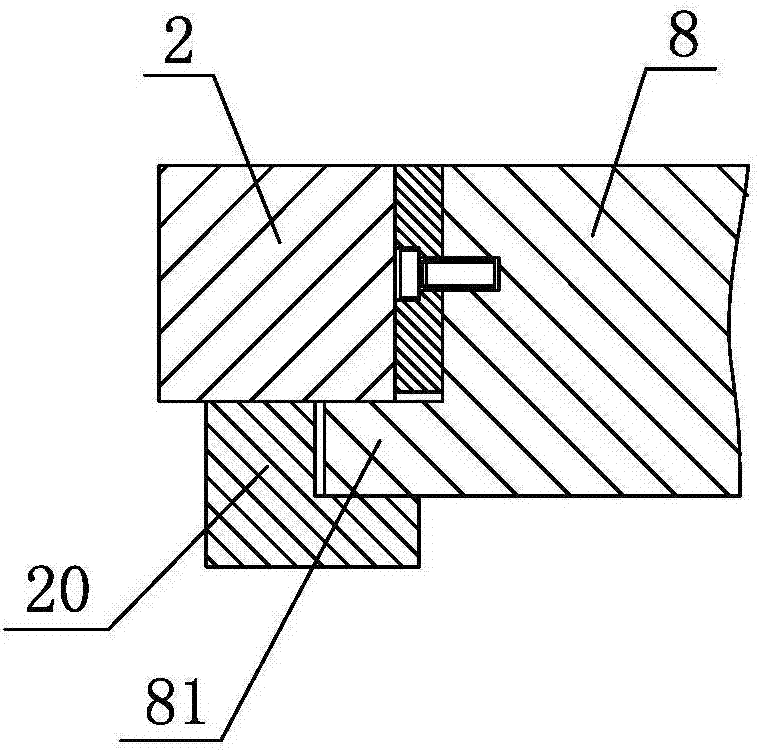
[0017] As shown in the figure, an integral cross wedge rolling mill driven by a hydraulic motor includes a working frame 1 and a transmission frame 2. The working frame 1 is provided with an upper roll system 3 and a lower roll system 4. On the working frame 1 A pressing system 5 for adjusting the distance between the upper roll system 3 and the lower roll system 4 is fixedly installed. The upper hydraulic motor 6 and the lower hydraulic motor 7 are installed on the transmission frame 2. The upper hydraulic motor 6 and the lower hydraulic motor 7 pass through the synchronous valve. (not shown in the figure) are respectively connected with the power source, the output shaft of the upper hydraulic motor 6 is coaxially fixedly connected with the upper roll in the upper roll system 3 through the coupling 61, and the output shaft of the lower hydrau...


PUM


Abstract

The invention discloses an integrated cross wedge rolling mill driven by a hydraulic motor. The integrated cross wedge rolling mill comprises a working rack and a driving rack, wherein the working rack is provided with an upper roller system and a lower roller system, the integrated cross wedge rolling mill is characterized in that the driving rack is provided with an upper hydraulic motor and a lower hydraulic motor, the upper hydraulic motor is coaxially and fixedly connected with an upper roller by a coupling, the lower hydraulic motor is coaxially and fixedly connected with a lower roller by a coupling, the driving rack is provided with a vertical adjusting mechanism used for adjusting the vertical direction of the upper hydraulic motor, and a displacement synchronous detection system is arranged between the upper hydraulic motor and the upper roller system. The integrated cross wedge rolling mill has the advantages that stepless speed adjustment can be achieved for the rotary speed of the upper and lower rollers, the torque is great, and low-speed large-tonnage movement can be achieved, so that the movement of the roller systems is uniform and steady; and furthermore, since the hydraulic motors are respectively coaxially and fixedly connected with the upper and lower roller systems by the couplings, the lateral dimension of the cross wedge rolling mill can be greatly reduced, the occupation space can be reduced, and the space utilization rate is improved.

Description

technical field [0001] The invention relates to a cross wedge rolling mill for processing shaft parts, in particular to an integral cross wedge rolling mill driven by a hydraulic motor. Background technique [0002] Cross wedge rolling is a high-efficiency material-saving forming processing technology for shaft parts. Compared with traditional cutting and forging, it has greatly improved material utilization, material saving rate and comprehensive performance of parts, and at the same time, the production cost has dropped by an average of 30%. about. However, the existing cross-wedge rolling mills basically transmit power and torque to the upper and lower rolls through mechanical transmission mechanisms such as motors and gearboxes. It is difficult to achieve speed adjustment for different rolling requirements without adding gearboxes; And because the rolling process of cross wedge rolling belongs to the plastic deformation of metal, the required rolling force is relatively...

Claims


Application Information

Patent Timeline
Patent Type & Authority Patents(China)
IPC IPC(8): B21B35/06B21B13/02
CPCB21B13/023B21B35/06
Inventor 束学道牛波凯彭文飞孙宝寿王英殷安民
Owner NINGBO UNIV
Why Eureka
Try Eureka