
Method and structure of brazing sealing and sealing of microcircuit module housing and cover plate

A technology for microcircuits and housings, applied in circuits, electrical components, welding equipment, etc., can solve the problems of easy sputtering or flow of solder and flux into the cavity of the housing, pollution of bare chips, etc., and achieve the purpose of inhibiting solder flow, Improvement of airtightness and reduction of leakage points

Active Publication Date: 2018-02-23
ZHUZHOU HONGDA MICROELECTRONICS TECH CO LTD
View PDF9 Cites 0 Cited by
  • Summary
  • Abstract
  • Description
  • Claims
  • Application Information

AI Technical Summary

Problems solved by technology

[0008] The technical problem to be solved by the present invention is: in the process of welding and sealing the cover plate and the shell of the microcircuit module, solder and flux are easy to sputter or flow into the cavity of the shell, causing pollution to the bare chip in the cavity , and propose a method that can prevent solder and flux from entering the cavity of the housing during sealing

Method used


Image

  • Method and structure of brazing sealing and sealing of microcircuit module housing and cover plate
  • Method and structure of brazing sealing and sealing of microcircuit module housing and cover plate
  • Method and structure of brazing sealing and sealing of microcircuit module housing and cover plate

Examples


Embodiment 1

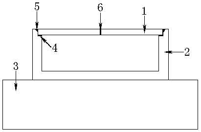
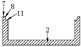
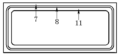
[0041] Such as figure 1 and figure 2 As shown, the cover plate 1 and the ┗-shaped casing step 11 on the casing 2 are covered on the casing 2. There is a microcircuit module in the casing 2, and a large number of bare chips are assembled in the microcircuit module. During brazing, the shell 2 is placed on the hot table 3 . A Y-shaped groove 8 is formed on the top 7 of the housing, and a ┗-shaped housing step 11 is provided below the Y-shaped groove 8 . When the cover plate 1 is closed on the ┗-shaped shell step 11 of the shell 2 , the Y-shaped groove 8 forms an annular groove gap between the cover plate 1 and the shell 2 . This is conducive to the flow of solder during brazing, making the brazing joint plump, improving the sealing performance, and effectively reducing the generation of leakage points. At the same time, the annular groove formed by the Y-shaped groove 8 can also prevent the solder from overflowing. effect.

[0042] Such as figure 1 and Figure 5 As shown,...


PUM

PropertyMeasurementUnit
melting pointaaaaaaaaaa
heightaaaaaaaaaa
widthaaaaaaaaaa

Abstract

The invention relates to a brazing sealing covering method for a shell and a cover plate of a microcircuit module. The method includes the following steps that the shell and the cover plate of the microcircuit module are machined and electroplated; after circuit assembling, the shell and the cover plate are subjected to brazing sealing; airtightness detection is completed, and leakage points are subjected to repair welding; the sealed module with the unqualified electrical property is uncovered to be reworked; and finally the outer surfaces of the shell and the cover plate of the qualified product are coated with three-proofing lacquer. The brazing sealing covering method has the advantages that the cover plate is simple in structure and easy to machine; soldering tin and soldering flux can be prevented from flowing into a cavity of the microcircuit module; the soldering tin is not prone to flowing everywhere, and the welded microcircuit module is attractive; and the brazing sealing covering method can be widely applied to sealing packaging of microcircuit modules of various types.

Description

technical field [0001] The invention relates to a sealing and capping method, in particular to a brazing sealing and capping method for a microcircuit module, which belongs to the technical field of electronic packaging. Background technique [0002] With the development of the electronics industry, microcircuit modules are widely used in various fields. Since a large number of bare chips are assembled in the cavity of the microcircuit module, and its assembly solder has a low melting point, in order to face various environments and ensure its performance for a long time, it must be sealed and packaged. [0003] Among the existing sealing methods for microcircuit modules, the brazing sealing method is suitable for the sealing of metal shells. It is simple to operate, low in cost, low in requirements for sealing equipment, good in sealing performance, and easy to repair and uncap. It is a widely used method. Highly reliable capping method. However, this method has its own d...

Claims


Application Information

Patent Timeline
Patent Type & Authority Patents(China)
IPC IPC(8): H01L21/00B23K1/00B23K101/36
CPCB23K1/0008B23K1/20B23K2101/36
Inventor 杨伟吴诗晗周志勇
Owner ZHUZHOU HONGDA MICROELECTRONICS TECH CO LTD
Learn More