A comprehensive test device for fault simulation and state detection of hydraulic pumps under variable working conditions

A fault simulation and state detection technology, applied in pump testing, liquid variable capacity machinery, machines/engines, etc., can solve problems such as variable speed of hydraulic pumps, poor reliability of test results, and poor completeness of measurement parameters, etc. To achieve the effect of complete parameter measurement and diverse functions

Active Publication Date: 2017-11-24
YANSHAN UNIV
View PDF7 Cites 2 Cited by
  • Summary
  • Abstract
  • Description
  • Claims
  • Application Information

AI Technical Summary

Problems solved by technology

There are many researches and test devices on hydraulic pump fault simulation and state detection at home and abroad, but most of the research work is carried out under the conditions of fixed working conditions, and there is a big gap compared with the actual working conditions, so it is difficult to use The research results are universal and universal
[0004] At present, although domestic and foreign technicians in the field have improved the above problems and proposed some test programs with variable loads, the following technical problems still exist: 1) The simulation of load changes is not real-time, and traditional manual methods are still used. The research on load adjustment method, fault signal acquisition and diagnosis method still belongs to the scope of fixed working condition diagnosis of hydraulic pump; 2) It does not involve the test method of variable speed of hydraulic pump, and it is impossible to realize the test simulation of speed fluctuation and variable speed condition , ignoring the impact of the speed change on the detection signal of the hydraulic pump; 3) The completeness of the measurement parameters is poor, only a single signal is measured and analyzed, and the reliability of the test results obtained is poor

Method used


Image

  • A comprehensive test device for fault simulation and state detection of hydraulic pumps under variable working conditions

Examples


Embodiment Construction

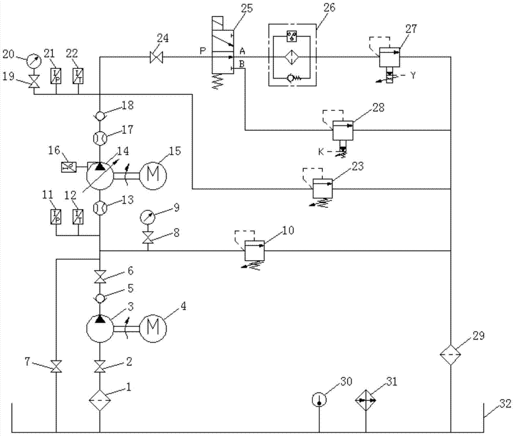
[0017] The present invention will be further described below in conjunction with accompanying drawing:

[0018] Such as figure 1 As shown, the test device of the present invention includes an oil suction filter 1, a first shut-off valve 2, an auxiliary oil supply pump 3, an auxiliary oil supply pump drive motor 4, a first one-way valve 5, a second shut-off valve 6, and a third shut-off valve 7. The first pressure gauge switch 8, the first pressure gauge 9, the first direct-acting relief valve 10, the first pressure sensor 11, the first temperature sensor 12, the first flow meter 13, the tested pump 14, the tested Pump drive motor 15, vibration sensor 16, second flowmeter 17, second one-way valve 18, second pressure gauge switch 19, second pressure gauge 20, second pressure sensor 21, second temperature sensor 22, second direct current Dynamic relief valve 23, fourth cut-off valve 24, two-position three-way electromagnetic reversing valve 25, pressure oil filter 26, electric p...


PUM


Abstract

The invention relates to a comprehensive testing device for fault simulation and state detection for a hydraulic pump under the variable working condition. The comprehensive testing device mainly comprises a plurality of parts of a load simulation module, a rotary speed simulation module, an auxiliary oil supplying system, a parameter measuring system and a tested pump, wherein the load simulation module is used for carrying out real-time loading simulation on the tested pump and can simulate load fluctuation and the impulse load working condition; the rotary speed simulation module is used for controlling the rotary speed of the tested pump in real time and simulating the variable speed working condition; the auxiliary oil supplying system is used for supplying certain oil absorption pressure to the tested pump; the parameter measuring system is used for collecting test data in real time; and the tested pump is a tested object for fault simulation or state detection. The comprehensive testing device can realize fault simulation of the hydraulic pump under the variable working condition, can control the working condition of the tested pump in real time, has the complete parameter measuring system and also has the function of detecting the state of the hydraulic pump.

Description

technical field [0001] The invention relates to a comprehensive hydraulic test device, in particular to a comprehensive test device for fault simulation and state detection of hydraulic pumps under variable working conditions. Background technique [0002] As a key system to improve the operation accuracy of mechanical equipment, the hydraulic control system must maintain good working condition and performance for the hydraulic components used. If a component fails, if it is not found and eliminated in time, it will have a great impact on the entire mechanical equipment. Cause huge economic losses, and even serious catastrophic accidents. [0003] The hydraulic pump is a typical mechanical-electrical-hydraulic integrated product with a complex internal structure. It is one of the core components that are prone to failure in the hydraulic system. Its quality directly affects the normal operation of the hydraulic system and also affects the use of other hydraulic components. ...

Claims


Application Information

Patent Timeline
Patent Type & Authority Patents(China)
IPC IPC(8): F04B51/00
CPCF04B51/00
Inventor 刘思远王闯杨梦雪
Owner YANSHAN UNIV
Why Eureka
Try Eureka