A thermal power plant power distribution room hot gas recovery device and its recovery process

A recovery device and power distribution room technology, which is applied in the direction of non-flammable liquid/gas transportation, lighting and heating equipment, blasting equipment, etc., can solve the problems of high operating costs, power consumption, frequent failures, etc., and achieve lower standards Effects of coal consumption, reduced cleaning work, and increased temperature

Active Publication Date: 2018-05-18
山东福宽生物工程有限公司
View PDF6 Cites 0 Cited by
  • Summary
  • Abstract
  • Description
  • Claims
  • Application Information

AI Technical Summary

Problems solved by technology

[0002] According to the design, the plant power distribution room of the thermal power plant is generally equipped with 10 sets of high and low voltage equipment, among which the equipment with higher power includes transformers, frequency conversion cabinets for primary fans, frequency conversion cabinets for secondary fans, frequency conversion cabinets for induced draft fans, and frequency conversion cabinets for water supply pumps , the capacity of these devices is mostly above 1000KW, and a large amount of heat will be released during operation. The room temperature in winter is generally about 20 degrees, and the room temperature in summer is as high as about 45 degrees. In order to protect the safe operation of electrical equipment, the hot air needs to be discharged outside. Generally, more than a dozen axial flow fans are used in the design, and the power is mostly ranging from 700W to 1500W. The control room where the high-voltage frequency converter is installed has higher requirements on the room temperature. Faults, the general design requires the installation of a large air conditioner with a power of more than 10KW, so the two methods not only require a relatively large investment for cooling, but also consume a lot of electric energy in vain, and the operating cost is relatively high

Method used


Image

  • A thermal power plant power distribution room hot gas recovery device and its recovery process

Examples


Embodiment Construction

[0014] The following will clearly and completely describe the technical solutions in the embodiments of the present invention with reference to the accompanying drawings in the embodiments of the present invention. Obviously, the described embodiments are only some, not all, embodiments of the present invention. Based on the embodiments of the present invention, all other embodiments obtained by persons of ordinary skill in the art without making creative efforts belong to the protection scope of the present invention.

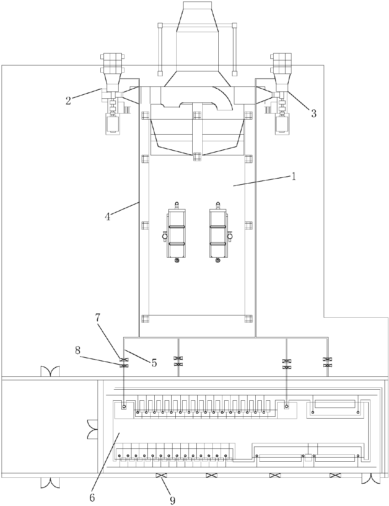
[0015] see figure 1 , the present invention provides a technical solution: a thermal power plant power distribution room hot gas recovery device, including a circulating fluidized bed boiler 1, the two sides of the circulating fluidized bed boiler 1 are respectively equipped with a boiler primary fan 2 and a boiler two The secondary fan 3, the primary fan 2 of the boiler and the secondary fan 3 of the boiler are connected with an air induction pipe 4, and the ...


PUM


Abstract

The invention discloses a recycling device for hot gas of a distribution room of a thermal power plant. The recycling device comprises a circulating fluidized bed boiler; a primary air fan of the boiler and a secondary air fan of the boiler are arranged on the two sides of the circulating fluidized bed boiler correspondingly and are connected with air guide pipes; the other ends of the air guide pipes are connected with a plurality of branch pipes; the other ends of the branch pipes are inserted into the side wall of the distribution room in a penetrating mode; an inner cavity of each branch pipe is connected with an isolation valve and a fireproof valve; and air inlets are evenly formed in the lower sides of the walls of the distribution room. The hot gas inside the distribution room of the thermal power plant is introduced into a hearth of the boiler through the pipes to participate in oxygen-assisted combustion mainly by means of the primary air fan of the boiler and the secondary air fan of the boiler, wasted hot gas is fully recycled, natural ventilation of the distribution room is increased for cooling, the equipment expense and operation expense invested for cooling of the distribution room are saved, and the standard coal consumption of the boiler is greatly reduced due to increasing of the temperature of air inlet gas of the air fans of the boiler.

Description

technical field [0001] The invention relates to the technical field of heat recovery devices, in particular to a thermal power plant power distribution room hot gas recovery device and a recovery process thereof. Background technique [0002] According to the design, the plant power distribution room of the thermal power plant is generally equipped with 10 sets of high and low voltage equipment, among which the equipment with higher power includes transformers, primary fan frequency conversion cabinets, secondary fan frequency conversion cabinets, induced draft fan frequency conversion cabinets, and water supply pump frequency conversion cabinets , the capacity of these devices is mostly above 1000KW, and a large amount of heat will be released during operation. The room temperature in winter is generally about 20 degrees, and the room temperature in summer is as high as about 45 degrees. In order to protect the safe operation of electrical equipment, the hot air needs to be ...

Claims


Application Information

Patent Timeline
Patent Type & Authority Patents(China)
IPC IPC(8): F23L5/04F23L5/02F23L9/00
CPCF23L5/02F23L5/04F23L9/00
Inventor 赵树平王继胜王兆林罗浩王兹兴程栾庆张振张宪伟蔡成云
Owner 山东福宽生物工程有限公司
Why Eureka
Try Eureka