Flue gas waste heat recovery system of 1000 MW secondary reheating power plant

A technology of waste heat recovery system and thermal power plant, applied in preheating, feed water heater, removal of solid residue, etc., can solve the problem of low energy level

Inactive Publication Date: 2020-09-18
DATANG DONGBEI ELECTRIC POWER TESTING & RES INST
View PDF4 Cites 1 Cited by
  • Summary
  • Abstract
  • Description
  • Claims
  • Application Information

AI Technical Summary

Problems solved by technology

[0005] At present, the existing flue gas waste heat utilization scheme in power plants is mainly to install low-temperature economizers at the inlet of the dust collector and the outlet of the induced draft fan in the tail flue of the boiler. ℃, the recovered flue gas waste heat generally replaces the last few stages of the steam turbine recuperation system with low-pressure steam extraction, which can reduce the standard coal consumption of the unit by about 1-2g / kw.h, and the energy level of flue gas waste heat utilization is low

Method used


Image

  • Flue gas waste heat recovery system of 1000 MW secondary reheating power plant

Examples


Embodiment Construction

[0019] The specific implementation manners of the present invention will be further described in detail below in conjunction with the accompanying drawings and embodiments. The following examples are used to illustrate the present invention, but are not intended to limit the scope of the present invention.

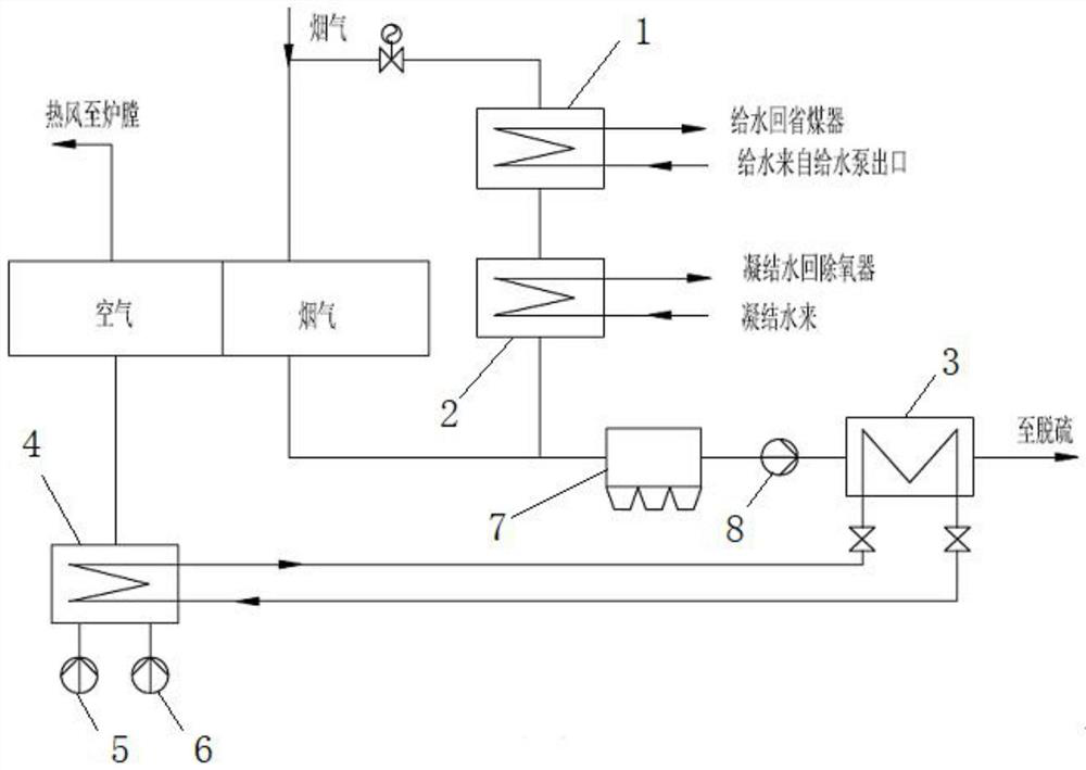
[0020] ginseng figure 1 As shown, this embodiment provides a 1000MW secondary reheating power plant flue gas waste heat recovery system, including a flue gas bypass installed on the boiler air preheater, and the flue gas bypass is provided with a first-stage bypass High-temperature heater 1 and bypass secondary low-temperature heater 2, bypass primary high-temperature heater 1 is used to heat the high-pressure feed water at the outlet of the turbine feed water pump, and bypass secondary low-temperature heater 2 is used to heat condensed water;

[0021] A low-temperature and low-pressure economizer 3 is installed at the inlet of the tail flue dust collector 7 at the outlet...


PUM


Abstract

The invention relates to a flue gas waste heat recovery system of a 1000 MW secondary reheating power plant. The system comprises a flue gas bypass arranged on an air preheater of a boiler, wherein abypass primary high-temperature heater and a bypass secondary low-temperature heater are arranged on the flue gas bypass, the bypass primary high-temperature heater is used for heating high-pressure feed water at an outlet of a feed water pump of a turbine, and the bypass secondary low-temperature heater is used for heating condensed water; and the inlet end of a flue dust remover at the tail partof an outlet of the air preheater of the boiler is provided with a low-temperature low-pressure economizer, and the low-temperature low-pressure economizer is used for heating cold air at an inlet ofthe air preheater through circulating water. According to the system, the boiler flue gas waste heat is utilized to simultaneously heat the condensed water, the cold air and the feed water, so that the energy level of low-temperature flue gas is improved, the waste heat utilization efficiency is greatly improved, the standard coal consumption of a unit is further reduced, the purposes of energy conservation and emission reduction are achieved, and the thermal economy of the unit is improved.

Description

technical field [0001] The invention belongs to the technical field of thermal power generation, and in particular relates to a 1000MW secondary reheat power plant exhaust waste heat recovery system. Background technique [0002] With the rapid development of my country's economy, the demand for electricity is increasing year by year, and more and more large-scale coal-fired thermal power generating units are put into use, which also makes the supply of coal resources increasingly tight. The power generation efficiency of generator sets and the reasonable and effective use of limited coal resources are particularly important. [0003] Power plant boilers are the most energy-consuming equipment in power plants, and are also the source of a series of energy-consuming processes in power plants. In order to generate the steam driven by the prime mover for power generation and ensure a large working capacity, the power station boiler consumes a large amount of coal resources. ...

Claims


Application Information

Patent Timeline
Patent Type & Authority Applications(China)
IPC IPC(8): F22D1/36F23J3/02
CPCF22D1/36F23J3/02
Inventor 康剑南王永宏张凯李帅王文铁王凤良马魁元王冠乔潘同洋
Owner DATANG DONGBEI ELECTRIC POWER TESTING & RES INST
Why Eureka
Try Eureka