Co-phasing control device and control method for spliced telescope

A technology for control devices and telescopes, applied in telescopes, optics, instruments, etc., can solve problems such as small detection range, and achieve the effects of improving real-time performance, large measurement range, good stability and robustness

Active Publication Date: 2016-06-22
SHANGHAI ASTRONOMICAL OBSERVATORY CHINESE ACAD OF SCI
View PDF6 Cites 31 Cited by
  • Summary
  • Abstract
  • Description
  • Claims
  • Application Information

AI Technical Summary

Problems solved by technology

Although this correction device can solve the problem of sign judgment and 2π ambiguity in phase translation error detection, the realization of this correction also needs to calibrate the p

Method used


Image

  • Co-phasing control device and control method for spliced telescope
  • Co-phasing control device and control method for spliced telescope
  • Co-phasing control device and control method for spliced telescope

Examples


Embodiment Construction

[0055] Below in conjunction with the drawings, preferred embodiments of the present invention are given and described in detail.

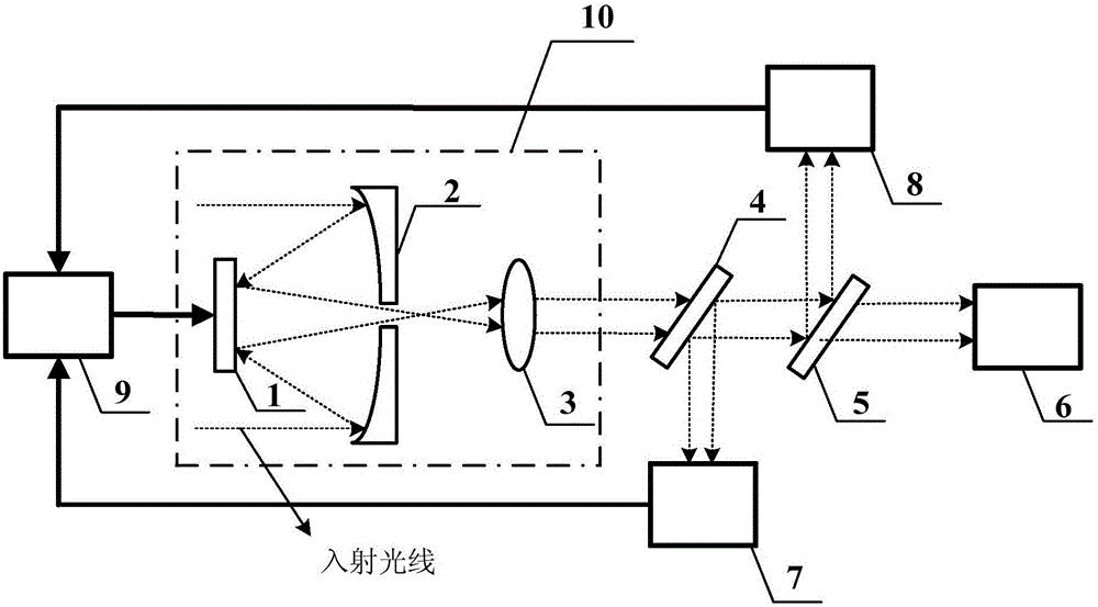
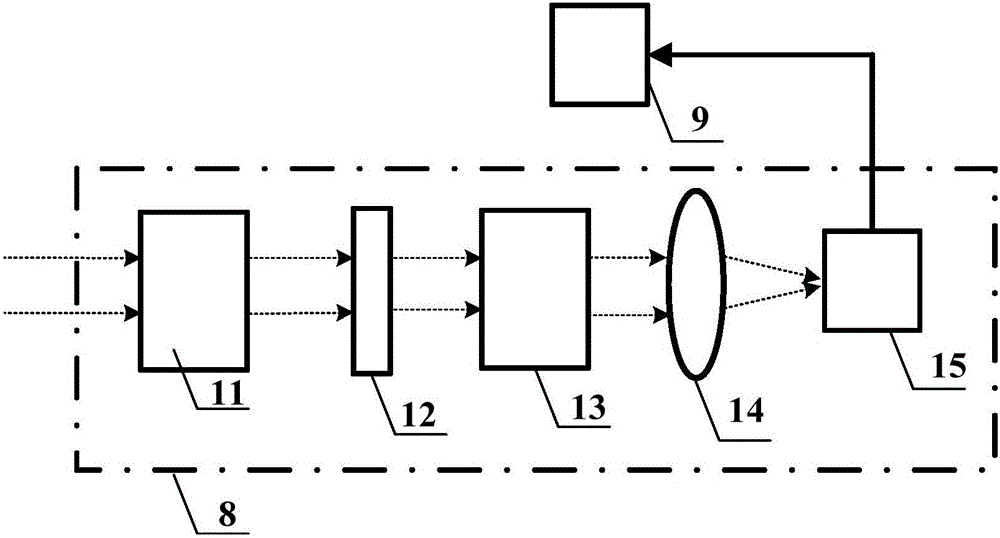
[0056] Such as figure 1 , 2 As shown, one of the present invention, that is, a co-phase control device for a spliced ​​telescope, includes: a spliced ​​telescope 10, a first beam splitter 4, a second beam splitter 5, an imaging system 6, a wavefront detector 7, a translation error Detector 8 and wavefront controller 9.

[0057] The spliced ​​telescope 10 receives peripheral incident light (such as starlight or ordinary broadband light) from the object to be measured, and generates parallel (or substantially parallel) outgoing light; the spliced ​​telescope 10 specifically includes: a separate deformable secondary mirror 1 with a driver , several splicing sub-mirrors 2 and eyepieces 3 (in the present embodiment, the splicing telescope 10 is a Cassegrain reflective telescope), wherein:

[0058] The splicing sub-mirror 2 is used to receive and refl...


PUM


Abstract

The invention relates to a co-phasing control device and control method for a spliced telescope.The device comprises a spliced telescope body, a first beam splitter, a wavefront detector, a second beam splitter, a translation error detector and a wavefront controller, wherein the first beam splitter receives emergent rays and generates first divided beams and second divided beams; the wavefront detector detects the first divided beams and obtains system aberration data and wavefront distortion aberration data of transmission paths of all spliced sub mirrors; the second beam splitter receives the second divided beams and generates third divided beams and fourth divided beams; the translation error detector detects the third divided beams and collects dispersion interference fringes between each pair of spliced sub mirrors; the wavefront controller is connected with the wavefront detector, the translation error detector and a driver of a secondary separating deformable mirror.By means of the co-phasing control device and control method for the spliced telescope, real-time detection and compensation and correction of translation, inclination and higher order aberration can be effectively achieved, and compared with the technology in a current similar system, better accuracy and instantaneity are achieved.

Description

technical field [0001] The invention relates to a splicing telescope co-phase control device and a control method. Background technique [0002] Using telescopes with high spatial resolution to better observe celestial bodies and the universe is the dream of astronomers and the goal pursued by builders of astronomical instruments. The spatial resolution of a telescope is proportional to its aperture, that is, the larger the aperture, the higher the resolution of the telescope. At present, the construction of single-mirror telescopes over 8 meters has been limited by factors such as manufacturing process and manufacturing cost. If you want to improve the spatial resolution of the telescope, you can use splicing mirror technology to build a larger-caliber telescope, such as the American Thirty Meter (TMT) Telescopes, ground-based Very Large Telescopes (GMTs), etc. all use splicing mirror technology. [0003] Splicing telescopes have great application potential in space remot...

Claims


Application Information

Patent Timeline
IPC IPC(8): G02B26/06G02B17/08G02B23/02G02B27/10
CPCG02B17/08G02B23/02G02B26/06G02B27/10
Inventor 颜召军陈欣扬朱能鸿
Owner SHANGHAI ASTRONOMICAL OBSERVATORY CHINESE ACAD OF SCI
Why Eureka
Try Eureka