Organic light-emitting pixel driving circuit and driving method thereof

A technology of pixel drive circuit and light-emitting current, which is applied in the direction of static indicators and instruments, can solve the problems of uneven brightness and dark display, the length of compensation phase, and long time, and achieve the effect of improving process fluctuation and fast charging

Active Publication Date: 2016-06-22
SHANGHAI TIANMA MICRO ELECTRONICS CO LTD +1
View PDF6 Cites 39 Cited by
  • Summary
  • Abstract
  • Description
  • Claims
  • Application Information

AI Technical Summary

Problems solved by technology

When the charging current is small and the capacity of capacitor C1 is large, charge the N1 node to the specified potential (V data -|V th |) will take longer
On the other hand, as the resolution of the display panel becomes higher and higher, the duration of the compensation phase of each pixel becomes shorter and shorter, resulting in insufficient charging of the capacitor C1, and the potential of the N1 node at the end of the compensation phase cannot reach the expected potential ( i.e. V data -|V th |) problem
When the charging current is not enough to make the potential of the N1 node reach the predetermined potential during the compensation phase, in order to meet the demand for the potential of the N1 node, on the one hand, V can be increased data The voltage value of the N1 node is used to compensate the potential of the N1 node, but this will undoubtedly increase the power consumption of the entire display panel
[0008] On the other hand, if the chan

Method used


Image

  • Organic light-emitting pixel driving circuit and driving method thereof
  • Organic light-emitting pixel driving circuit and driving method thereof
  • Organic light-emitting pixel driving circuit and driving method thereof

Examples


Embodiment Construction

[0023] The application will be further described in detail below in conjunction with the accompanying drawings and embodiments. It should be understood that the specific embodiments described here are only used to explain related inventions, rather than to limit the invention. It should also be noted that, for the convenience of description, only the parts related to the invention are shown in the drawings.

[0024] It should be noted that, in the case of no conflict, the embodiments in the present application and the features in the embodiments can be combined with each other. The present application will be described in detail below with reference to the accompanying drawings and embodiments.

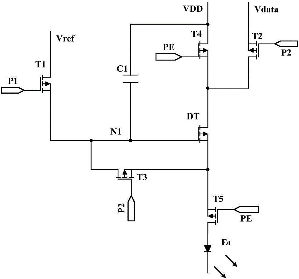
[0025] see figure 2 Shown is a schematic structural diagram of an embodiment of the organic light-emitting pixel driving circuit of the present application.

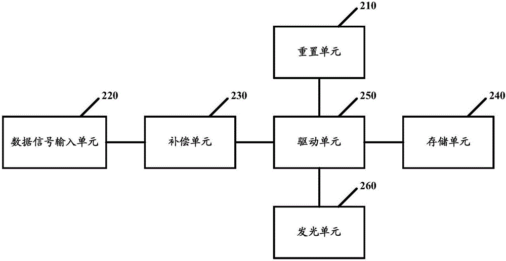
[0026] The organic light emitting pixel driving circuit of this embodiment includes a reset unit 210 , a data signal input...


PUM


Abstract

The application discloses an organic light-emitting pixel driving circuit and a driving method thereof. The organic light-emitting pixel driving circuit comprises a reset unit, a data signal input unit, a compensation unit, a storage unit, a driving unit and a light-emitting unit. The driving unit generates light emission current based on a data signal and provides light emission current to the light-emitting unit. The driving unit comprises a first driving transistor and a second driving transistor which are connected in series and have a common gate electrode. The first driving transistor is used for storing the data signal to the storage unit in the compensation phase. The first driving transistor and the second driving transistor are used for providing light emission current to a light-emitting diode in the light emission phase. According to the scheme, current of the compensation phase is relatively high so that the data signal is enabled to be rapidly stored to the storage unit.

Description

technical field [0001] The present disclosure generally relates to display technology, and in particular, relates to an organic light emitting pixel driving circuit and a driving method thereof. Background technique [0002] With the continuous development of display technology, the sizes and specifications of displays are changing with each passing day. For example, in order to meet the portability of electronic devices, the demand for smaller size display screens continues to increase. [0003] In addition, with the development of display technology, users have higher requirements on the display quality of the display screen. For example, users tend to prefer high PPI (PixelsperInch, pixels per inch) display to improve the accuracy and consistency of the display. The OLED (Organic Light-Emitting Diode, Organic Light-Emitting Diode) display is more and more widely used in various portable electronic devices because of its thinness, power saving and other characteristics. ...

Claims


Application Information

Patent Timeline
IPC IPC(8): G09G3/3233G09G3/3283
CPCG09G3/3233G09G3/3283G09G2320/0204
Inventor 钱旭翟应腾
Owner SHANGHAI TIANMA MICRO ELECTRONICS CO LTD
Why Eureka
Try Eureka