High-frequency transformer spool

A high-frequency transformer, winding frame technology, applied in inductor/transformer/magnet manufacturing, coil manufacturing, electrical components, etc., can solve problems such as unusability and copper wire winding

Active Publication Date: 2016-06-22
贵州鑫湄纳米科技有限公司
View PDF5 Cites 3 Cited by
  • Summary
  • Abstract
  • Description
  • Claims
  • Application Information

AI Technical Summary

Problems solved by technology

[0004] The present invention intends to provide a high-frequency transformer winding frame to solv

Method used


Image

  • High-frequency transformer spool
  • High-frequency transformer spool

Examples


Embodiment 1

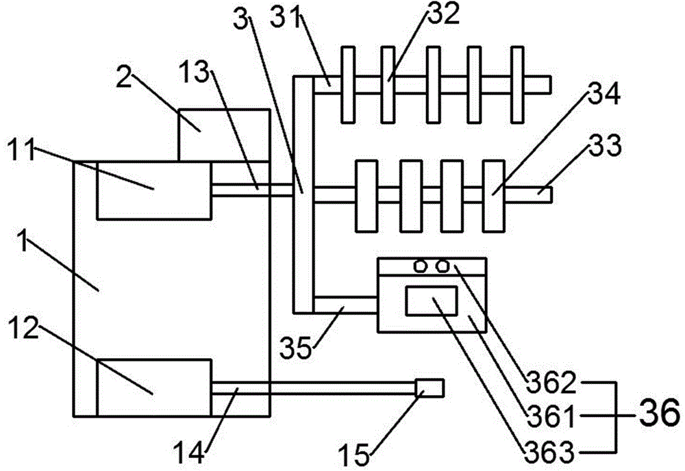
[0023] figure 1 The high-frequency transformer bobbin shown includes a box body 1, a control system 2, a bracket 3, a first motor 11 and a second motor 12, and the control system 2 connects the first motor 11 and the second motor 12 through wires. The motor 11 and the second motor 12 are installed in the box 1 body. The first motor 11 is a straight step motor, and the second motor 12 is a step motor. The straight stepping motor can push the bracket to move laterally, and can process the magnetic core with the rotation of the stepping motor. The straight stepping motor is fixed on the top in the casing 1 by bolts, and the stepping motor is fixed on the bottom in the casing 1 by bolts. The bolts fix the linear motor and the stepper motor, which can prevent the vibration during work from affecting the processing of the high-frequency transformer.

[0024] One side of the box body 1 is the winding side, and two through holes are arranged on the winding side, corresponding to th...

Embodiment 2

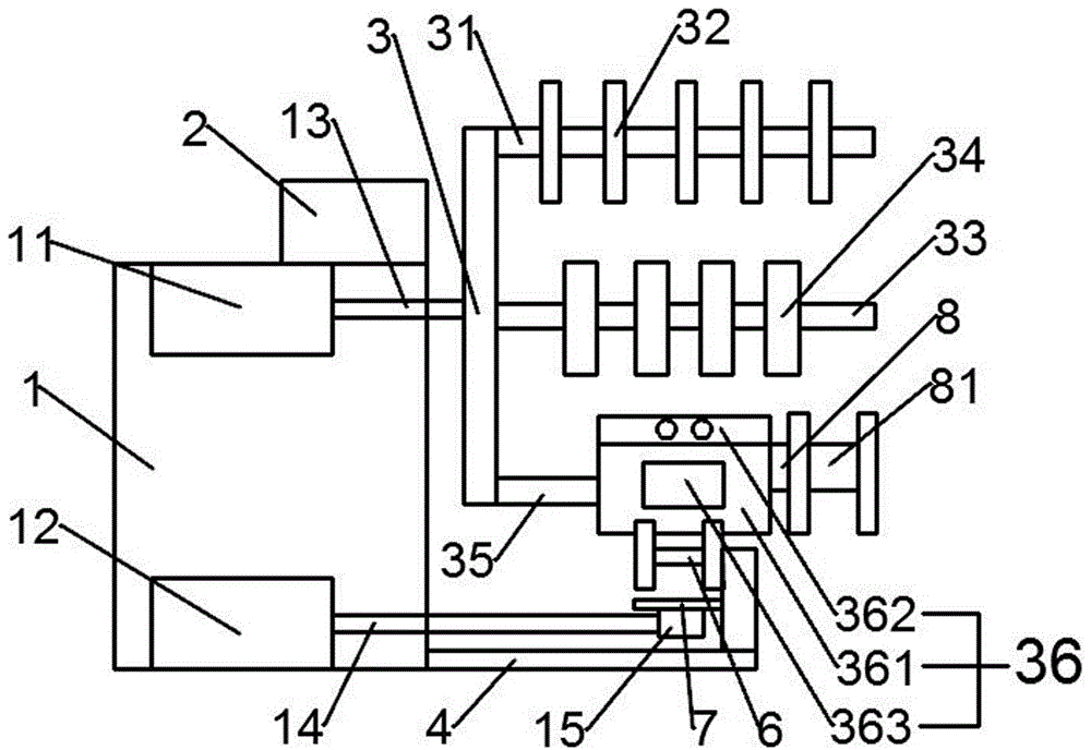
[0028] figure 2 The bottom of the winding side as shown is fixed with a base 4, a vertical plate 5 is fixed on the base 4, a cross bar 6 is arranged on the top of the vertical plate 5, two spacers 32 are arranged on the cross bar 6, and the vertical plate 5 There are two pipe columns 7 fixed in the middle, which is to prevent the insulation tape from falling off and sticking to dust and foreign matter when it is not in use, which will affect the processing of the high-frequency transformer. The insulating tape can be placed on the cross bar 6, and the insulating tape passes through the pipe column 7, which is convenient for the operator to use the insulating tape to process the high-frequency transformer.

[0029] The hub 36 is fixedly connected with the wire management holder 8 , and the wire management holder 8 includes a round tube 81 and spacers 32 arranged at both ends of the round tube 81 . The wire management reel is directly installed between the spacers 32 of the wi...


PUM


Abstract

The invention belongs to the field of high-frequency transformer equipment, and particularly relates to a high-frequency transformer spool. The high-frequency transformer spool comprises a box body, a control system, a bracket, a first motor and a second motor, wherein a winding side is arranged at one side of the box body; two through holes are formed in the winding side, and correspond to the first motor and the second motor respectively; the first motor is fixedly connected to a bracket shaft; the bracket shaft extends out of the through holes and is fixedly connected with the bracket; a placement rod is fixed at the top part of the bracket; at least five spacers are fixed on the placement rod; a line tube rod is fixed at the middle part of the bracket; at least four line tubes vertical to the line tube rod are fixed on the line tube rod; a line concentrating rod is fixed at the bottom part of the bracket; a line concentrator is fixed on the line concentrating rod; and a winding shaft is fixedly connected to the second motor, extends out of the through holes and is fixedly connected with a fixed block. The problem that a copper wire coil of a copper wire barrel is intertwined and cannot be used is solved by providing the high-frequency transformer spool capable of separating the copper wire coil.

Description

technical field [0001] The invention belongs to the field of high-frequency transformer equipment, and in particular relates to a winding frame of a high-frequency transformer. Background technique [0002] High-frequency transformer is a power transformer whose operating frequency exceeds intermediate frequency (10kHz). It is mainly used as a high-frequency switching power transformer in high-frequency switching power supplies, and is also used as a high-frequency inverter in high-frequency inverter power supplies and high-frequency inverter welding machines. power transformer. [0003] In the production of high-frequency transformers, winding frames are required to wind copper wires for the magnetic cores of high-frequency transformers. In addition to the existing high-frequency transformer winding frame including a box body, a control system, a bracket and two motors installed in the box body, the copper wire coil of the copper wire barrel is required to provide the copp...

Claims


Application Information

Patent Timeline
IPC IPC(8): H01F41/092H01F41/12
CPCH01F41/125
Inventor 冯涛
Owner 贵州鑫湄纳米科技有限公司
Why Eureka
Try Eureka