
Method and equipment for determining road network partitioning border line

A boundary line and road network technology, applied in road network navigator, service based on location information, geometric CAD, etc., can solve problems such as jumps and achieve accurate determination

Active Publication Date: 2016-06-22
IBM CORP
View PDF4 Cites 3 Cited by
  • Summary
  • Abstract
  • Description
  • Claims
  • Application Information

AI Technical Summary

Problems solved by technology

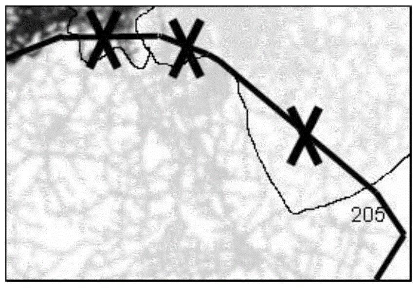
Since road network data in different regions are usually placed in different servers, this will cause requests to continuously jump between servers
[0006] From the above, it can be seen that there is still room for improvement in the road network partition boundary line determination scheme in the prior art

Method used


Image

  • Method and equipment for determining road network partitioning border line
  • Method and equipment for determining road network partitioning border line
  • Method and equipment for determining road network partitioning border line

Examples


Embodiment Construction

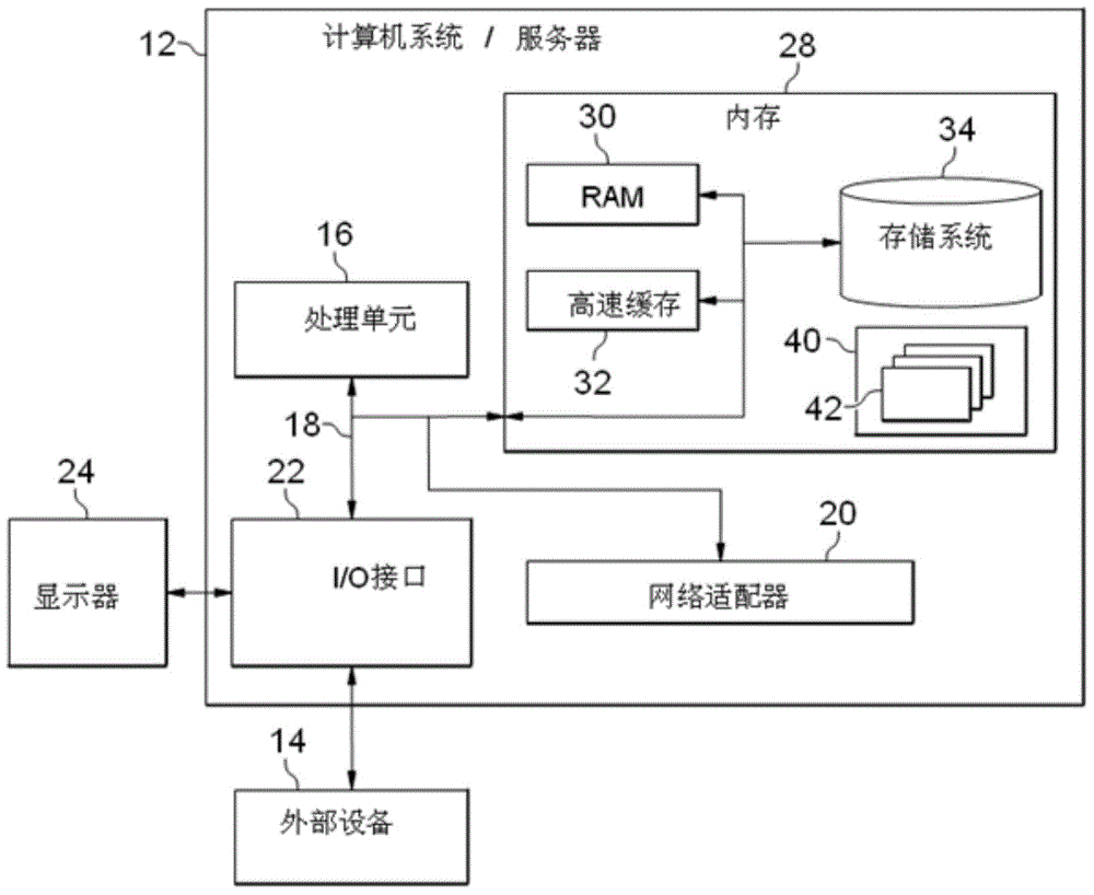
[0029] Preferred embodiments of the present disclosure will be described in more detail below with reference to the accompanying drawings. Although preferred embodiments of the present disclosure are shown in the drawings, it should be understood that the present disclosure may be embodied in various forms and should not be limited to the embodiments set forth herein. Rather, these embodiments are provided so that this disclosure will be thorough and complete, and will fully convey the scope of the disclosure to those skilled in the art.

[0030] figure 1 A block diagram of an exemplary computer system / server 12 suitable for use in implementing embodiments of the invention is shown. figure 1 The computer system / server 12 shown is only an example and should not impose any limitation on the functions and scope of use of the embodiments of the present invention.

[0031] Such as figure 1 As shown, computer system / server 12 takes the form of a general purpose computing devic...


PUM


Abstract

An embodiment of the invention discloses a technical scheme of determining a border line between road network partitions, in particular to a method and equipment for determining a road network partitioning border line. The method comprises the steps of: determining a border point based on road network data and partitioning information of road segments in the road network; determining a buffer zone between adjacent partitions based on the border point, the partitioning information of the road segments, and the road network data; and determining a border line between the adjacent partitions based on the buffer zone. Through adoption of the method and the equipment provided by the invention, the border lines for road network partitions can be accurately determined.

Description

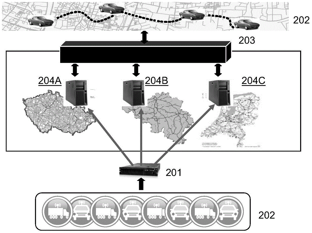
technical field [0001] Embodiments of the present invention relate to the field of road network data processing, and more specifically, to a method and device for determining boundary lines of various partitions in a road network. Background technique [0002] Nowadays, location-based services are more and more widespread, Figure 2A The Internet of Vehicles system shown is a common location-based service. Figure 2A In the shown Internet of Vehicles system, a distributed server environment is usually used, so that when providing online location-based Internet of Vehicles services, it can not only ensure scalability, but also support the collection and processing of large-scale vehicle data. [0003] In view of the spatial characteristics of in-vehicle data and Internet of Vehicles service requests, load distribution based on road network segmentation is an effective distributed strategy, which divides the entire road network into multiple regions (such as Figure 2A The road...

Claims


Application Information

Patent Timeline
Patent Type & Authority Applications(China)
IPC IPC(8): H04L29/08H04W4/02
CPCG06F30/18G01C21/3815G01C21/3867
Inventor 胡国强段宁张欣董维山高鹏
Owner IBM CORP
Learn More