Engine unit and vehicle

An engine and four-stroke engine technology, applied in the field of vehicles, can solve the problems of reducing the mountability and increasing the size of the starter motor.

Active Publication Date: 2016-06-22
YAMAHA MOTOR CO LTD
View PDF7 Cites 4 Cited by
  • Summary
  • Abstract
  • Description
  • Claims
  • Application Information

AI Technical Summary

Problems solved by technology

However, if the output torque of the starter motor is increased, the size of the starter...

Method used


Image

  • Engine unit and vehicle
  • Engine unit and vehicle
  • Engine unit and vehicle

Examples


no. 1 example

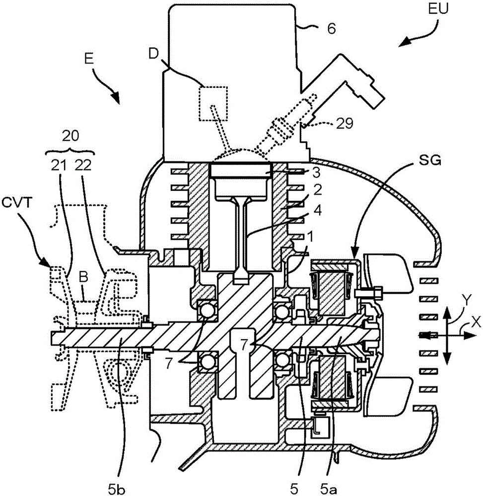
[0082] figure 1 A cross-sectional view schematically showing a schematic configuration of part of the engine unit EU according to the first embodiment of the present invention. The engine unit EU of this embodiment is a four-stroke engine unit for a vehicle.

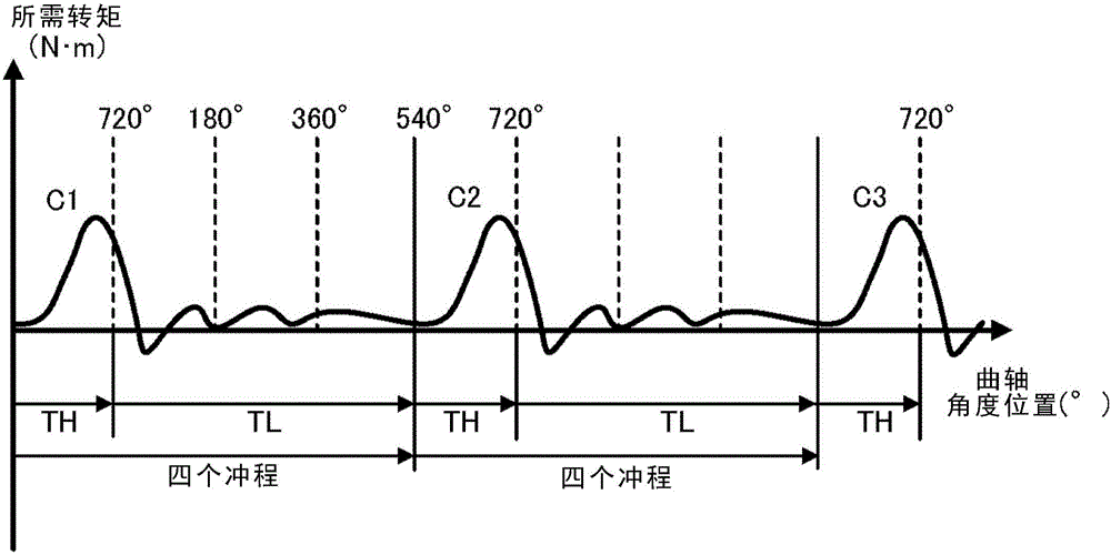
[0083] The engine unit EU is mounted on a motorcycle as an example of a vehicle (refer to Figure 14 )middle. The engine unit EU includes a four-stroke engine body E and a three-phase brushless motor SG. The four-stroke engine body E is a single-cylinder four-stroke engine. The four-stroke engine body E has figure 2 Angular position of the crank is shown as a function of torque required.

[0084] figure 2 An explanatory diagram schematically showing the relationship between the crank angle position and the required torque when the engine is started.

[0085] The four-stroke engine body E includes a high load region TH in which the rotational load of the crankshaft 5 is greater during four strokes, and a low load...

no. 2 example

[0171] Next, a second embodiment of the present invention will be described. In the following description of the second embodiment, elements corresponding to those of the first embodiment are given the same reference numerals, and differences from the above-mentioned first embodiment will be mainly described.

[0172] The four-stroke engine body E provided in the engine unit EU of the present embodiment has a decompression device (decompressor). exist figure 1, a decompression device D is schematically shown. The decompression device D discharges a part of the gas of the combustion chamber by opening a valve provided in the four-stroke engine body E during a part of the compression stroke. That is, the pressure relief device D relieves the pressure of the combustion chamber during a portion of the compression stroke. Thereby, the influence of the compression reaction force of gas received by the crankshaft 5 is reduced. That is, in the high load region, the load to rotate ...

no. 3 example

[0188] Next, a third embodiment of the present invention will be described. In the following description of the third embodiment, elements corresponding to those of the first embodiment are given the same reference numerals, and differences from the above-mentioned first embodiment will be mainly described.

[0189] Figure 10 It is a flowchart explaining the operation of the engine unit EU of the third embodiment. Figure 11 It is a figure explaining the operation|movement of the crankshaft 5 of the engine unit EU of 3rd Embodiment.

[0190] In the engine unit EU of the present embodiment, the control device CT stops the rotation of the crankshaft 5 ( Figure 10 In the position of S12), the normal rotation and reverse rotation of the crankshaft 5 are switched (S301) in the state where the start instruction is not received.

[0191] For example, if the forward rotation stop position of the crankshaft 5 continued from the stop of the combustion operation of the four-stroke e...


PUM


Abstract

The present invention provides an engine unit and the like that has a high-load region and a low-load region, and after a combustion halt instruction, can achieve both a reduction in the time until restarting and mountability to a vehicle. The engine unit is provided with a four-stroke engine body, a three-phase brushless motor, an inverter, and a control device. After the combustion operation of the four-stroke engine body and the positive rotation of a crankshaft have halted, the control device controls a plurality of switching units of the inverter in the state of the combustion operation of the four-stroke engine body and the positive rotation of a crankshaft being halted and there being no input of a startup instruction, and as a result the voltage from the battery imposed on the three-phase brushless motor is controlled, and the crankshaft is caused to rotate in the positive direction from a stopped position until the compression stroke of the four strokes. When there has been the input of a startup instruction, the control device causes the positive rotation of the crankshaft from the position of the crankshaft at the point in time the startup instruction has been input.

Description

technical field [0001] The present invention relates to an engine unit including a four-stroke engine body having a high-load region and a low-load region during four strokes, and a vehicle equipped with the engine unit. Background technique [0002] As an engine equipped in a vehicle, there is a four-stroke engine (for example, a single-cylinder engine) that has a high-load region where the load to rotate the crankshaft of the engine is large during four strokes, and a low load to rotate the crankshaft. Small low load areas. This four-stroke engine requires a large output torque from the starter motor in order to rotate the crankshaft against a high load region when the engine is started. However, if the output torque of the starter motor is increased, the size of the starter motor needs to be increased, and thus the mountability of the engine unit on the vehicle is reduced. Improvement in vehicle mountability is expected for engine units. [0003] Patent Document 1 (PTL...

Claims


Application Information

Patent Timeline
IPC IPC(8): F02N11/08F02D29/02F02N11/04
CPCF02N11/04F02N11/08F02D41/062F02N19/005F02N2011/0896F02N2250/04F02N19/004
Inventor 西川贵裕日野阳至
Owner YAMAHA MOTOR CO LTD
Why Eureka
Try Eureka