
Automatic comb handle assembling and welding machine

An automatic assembly and welding machine technology, applied in welding equipment, welding equipment, auxiliary welding equipment, etc., can solve the problems of inability to ensure that the cover plate is completely closed, low production efficiency, and high scrapping rate of comb handles

Active Publication Date: 2016-06-29
NINGBO RAVO IND GRP CO LTD
View PDF8 Cites 10 Cited by
  • Summary
  • Abstract
  • Description
  • Claims
  • Application Information

AI Technical Summary

Problems solved by technology

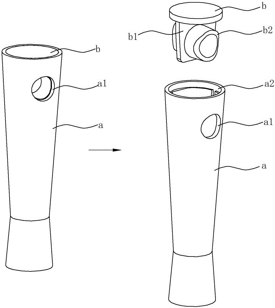
Manual assembly is not only low in production efficiency, but also requires a lot of manpower and material resources. Moreover, when assembling, it is necessary to strictly align the two ends of the tubular body with the two ends of the through hole, otherwise there will be a problem of deviation in the position of the hanging hole. , and due to the instability of human factors, the above-mentioned hanging hole deviation problem caused by manual assembly is inevitable; at the same time, after manually inserting the tubular body into the handle, it is impossible to ensure that the cover plate is completely closed on the upper port of the handle. If there is a deviation in the matching position between the cover plate and the upper port of the handle, it will seriously affect the aesthetics and firmness of the comb handle; in short, the existence of the above problems will greatly affect the overall quality of the comb handle after assembly, resulting in The scrap rate is high and the pass rate is low, which increases the production cost of the comb handle to a certain extent and reduces the production profit of the enterprise.

Method used


Image

  • Automatic comb handle assembling and welding machine
  • Automatic comb handle assembling and welding machine
  • Automatic comb handle assembling and welding machine

Examples


Embodiment Construction

[0057] The present invention will be further described in detail below in conjunction with the accompanying drawings and embodiments.

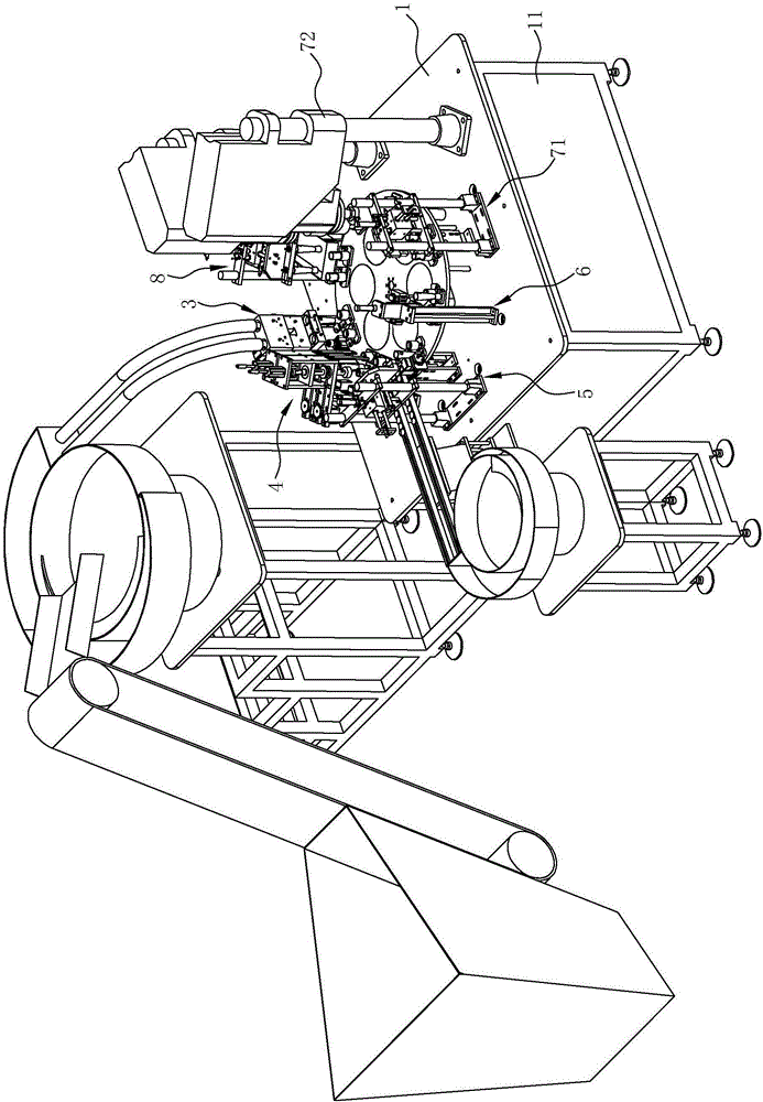
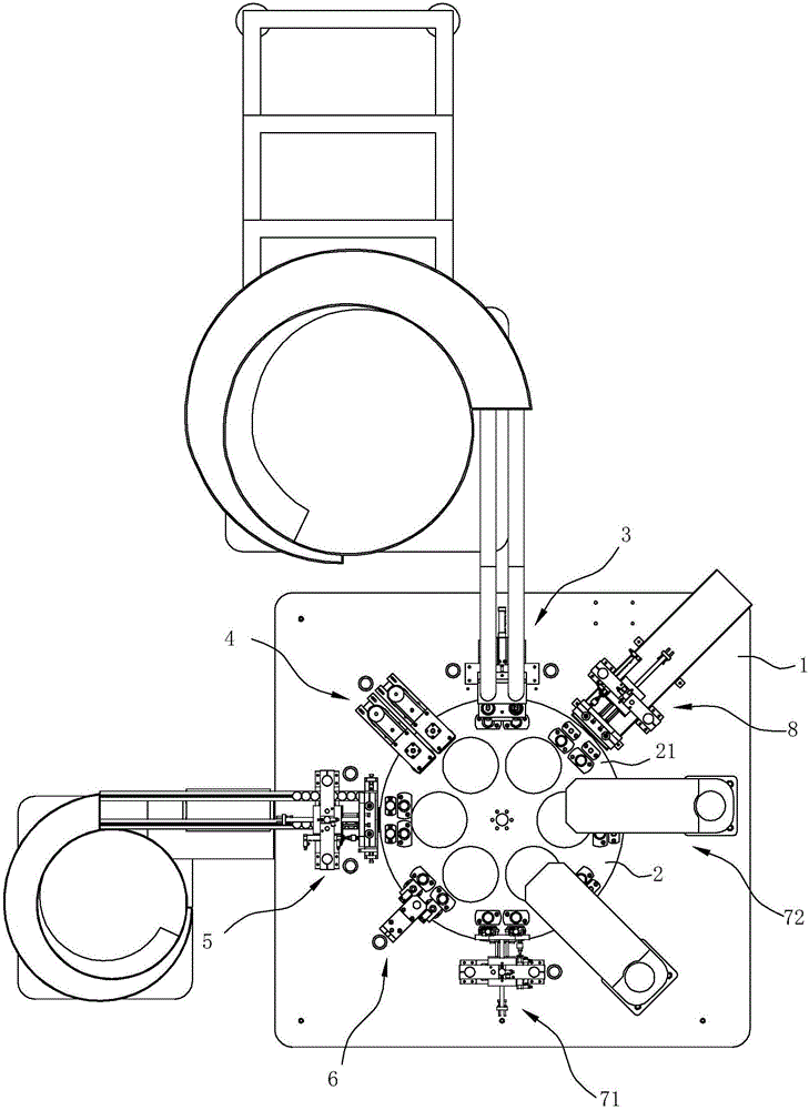
[0058] Such as Figure 2-21 As shown, the comb handle automatic assembly and welding machine of this embodiment includes an assembly platform 1, a turntable 2, a first drive mechanism 10, a handle removal mechanism 3, a handle positioning mechanism 4, a bottom cover removal mechanism 5, a detection mechanism 6, a welding Mechanism 7 and finished product output mechanism 8. The assembly platform 1 is used to provide an operating platform for the assembly of the comb handle, and the automatic assembly process of the comb handle in this embodiment is completed on the assembly platform 1 .

[0059] The assembly platform 1 is supported on the ground by a mounting frame 11 , and the turntable 2 is disc-shaped and rotatably arranged on the assembly platform 1 . The bottom of the turntable 2 is supported on the assembly platform 1 by four support ar...


PUM


Abstract

The invention relates to an automatic comb handle assembling and welding machine which comprises an assembling platform, a rotary disc, a first drive mechanism, a handle moving and taking mechanism, a bottom cover moving and taking mechanism, a handle locating mechanism, a welding mechanism and a finished product output mechanism. The handle moving and taking mechanism is used for moving and taking handles to mold seats on the edge of the rotary disc. The handle locating mechanism is used for rotating the handles into the state that through holes in the upper ends of the handles are aligned with tubular bodies on bottom covers. The bottom cover moving and taking mechanism is used for moving and taking the bottom covers to the positions above the mold seats and arranging the bottom covers in upper ports of the handles. The welding mechanism is used for ultrasonically welding the bottom covers and the handles. Compared with a manual assembling process in the prior art, the automatic comb handle assembling and welding machine is convenient to use, and the assembling efficiency of the comb handles is greatly improved; due to the fact that the whole process is automatically operated and controlled for operation through a master control program, influences caused by manual factors are reduced, the handles and the bottom covers are accurately aligned, welding is firm, the comb handles produced in the same batch are high in quality stability, the production cost of the comb handles is reduced to a great extent, and the productive profit of an enterprise is improved.

Description

technical field [0001] The invention relates to the technical field of comb production and manufacturing, in particular to a comb handle automatic assembly welding machine. Background technique [0002] At present, there are various combs on the market, including square, round, oval combs without handles, and combs with handles. Among them, the structure of combs with handles is also very different. The comb handle and comb body are integrally formed, and some comb handles and comb bodies are formed into two independent individuals during production, and the two are assembled later. For the latter, there is usually a hanging hole for hanging on the comb handle. Since the comb handle generally runs through up and down, it is necessary to set a bottom cover at one end of the comb handle. On the one hand, one end of the comb handle is sealed. On the other hand, A tubular body capable of matching with the hanging hole can be arranged on the bottom cover, so that the hanging hol...

Claims


Application Information

Patent Timeline
IPC IPC(8): B23K20/10B23K20/26B23K37/04
CPCB23K20/10B23K20/26B23K37/0443
Inventor 陈奇伟相琼颖
Owner NINGBO RAVO IND GRP CO LTD
Learn More