A 3D additive T-shaped structure double-sided laser welding method

A technology of laser welding and welding method, applied in laser welding equipment, welding equipment, metal processing equipment and other directions, can solve the problems of difficult to ensure welding wire, difficult to weld structure alloy control, etc., achieve high density, uniform alloy control, improve The effect of mechanical properties

Active Publication Date: 2017-08-25
HARBIN INST OF TECH
View PDF7 Cites 1 Cited by
  • Summary
  • Abstract
  • Description
  • Claims
  • Application Information

AI Technical Summary

Problems solved by technology

[0004] In order to solve the problem of high welding speed and long welding bead, the double-sided laser welding process of T-shaped structure is difficult to ensure that the welding wire is continuously and stably fed into the molten pool at a constant speed, and one-time welding can obtain uniform, continuous and defect-free double-sided welding. It is difficult to flexibly control the specific alloy of the weld seam, and a 3D additive T-shaped structure double-sided laser welding method is proposed.

Method used


Image

  • A 3D additive T-shaped structure double-sided laser welding method
  • A 3D additive T-shaped structure double-sided laser welding method
  • A 3D additive T-shaped structure double-sided laser welding method

Examples


specific Embodiment approach 1

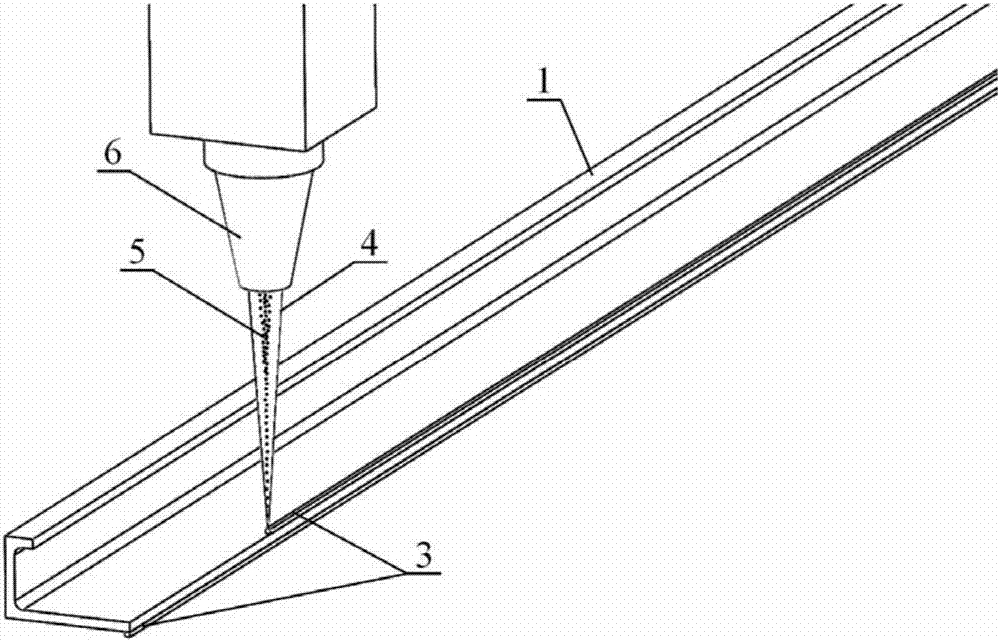
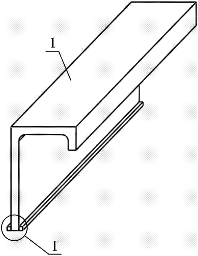
[0019] Specific implementation mode 1: Combination Figure 1 ~ Figure 4 To explain this embodiment, the welding method of this embodiment is to weld the T-shaped structure of the aircraft wall panel. The T-shaped structure is welded by the vertically placed long stringer 1 and the horizontally placed skin 2. The specific welding method is through The following steps are achieved:

[0020] Step 1. Chemically clean the surface of the long stringer 1 to remove the oxide film and oil stains;

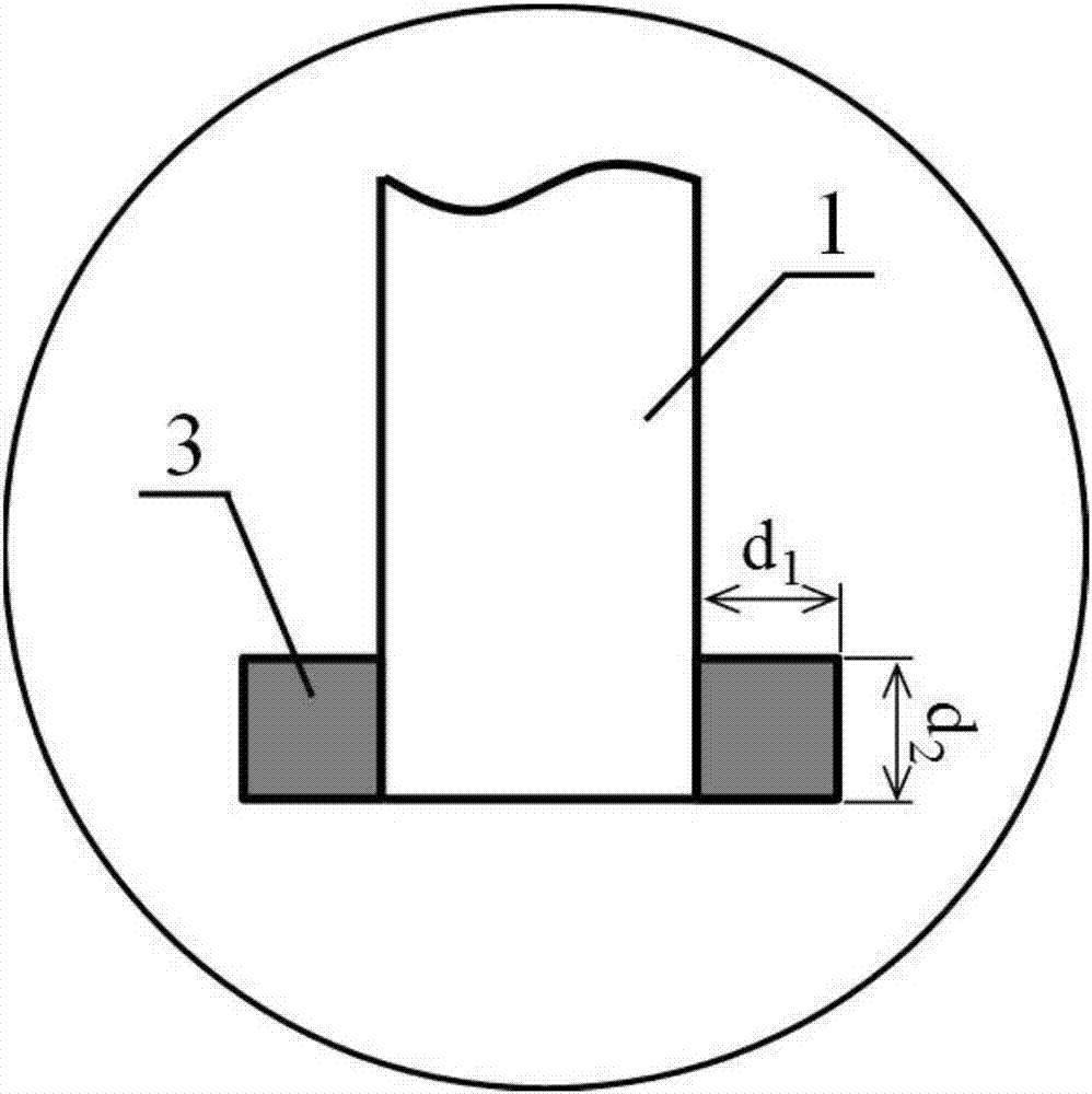
[0021] Step 2. Designing the deposition layer 3: Design the deposition layer 3 on the area to be welded on the surface of the long stringer 1, and the cross section of the deposition layer 3 is square or rectangular;

[0022] Step 3. Place the laser cladding head 6 vertically directly above the area to be welded on the surface of the long stringer 1, and use the laser beam 4 to feed the alloy powder 5 coaxially, and perform laser 3D on the area to be welded on both sides of the stringer 1 Add mat...

specific Embodiment approach 2

[0024] Specific implementation manner two: combination image 3 To describe this embodiment, this embodiment is when the cross section of the deposition layer 3 in step 2 is square, that is, d 1 =d 2 , D 1 And d 2 Meet the following relationship: d 1 ·D 2 =π·r 2 ·V / V, where d 1 Is the width of the deposition layer, d 2 Is the height of the deposition layer, r is the radius of the welding wire used in conventional double-sided laser filler wire welding, v is the wire feeding speed, and V is the welding speed. The other steps are the same as in the first embodiment.

specific Embodiment approach 3

[0025] Specific implementation mode three, combination image 3 To describe this embodiment, the cross section of the deposition layer 3 in step 2 is rectangular, that is, d 1 ≠d 2 , D 1 And d 2 Meet the following relationship: d 1 ·D 2 =π·r 2 ·V / V, where r is the radius of the welding wire used in conventional double-sided laser filler wire welding, v is the wire feeding speed, and V is the welding speed. The other steps are the same as in the first embodiment.


PUM


Abstract

The invention provides a 3D additive-manufacturing bilateral laser welding method for a T-shaped structure, relates to a double-laser-beam welding method, and aims to solve the problems that under the conditions of high welding speed and long weld beads, in a bilateral laser welding process of a T-shaped structure, the circumstance that welding wires are continuously and stably fed into a molten pool at constant speed and even, coherent and non-defective bilateral weld joints are obtained by one-time welding is difficult to ensure, and alloy of weld microstructures is difficult to regulate and control specifically and flexibly. The method comprises the following steps: 1, chemically cleaning the surface of a stringer; 2, designing of a sedimentary layer: designing the sedimentary layer in a region to be welded on the surface of the stringer, wherein the cross section of the sedimentary layer is square or rectangular; 3, vertically placing a laser cladding head at a position right above the region to be welded on the surface of the stringer, carrying out laser 3D additive-manufacturing on regions to be welded on two sides of the stringer to obtain the sedimentary layer in a mode of coaxially feeding laser beams and alloy powder; and 4, carrying out bilateral laser welding on the stringer and an envelope to obtain bilateral symmetric weld joints. The 3D additive-manufacturing bilateral laser welding method for the T-shaped structure is used for double-laser welding of the T-shaped structure.

Description

Technical field [0001] The invention relates to a double laser beam welding method, in particular to a 3D additive T-shaped structure double-sided laser welding method, which can be applied to the welding process of long stringers and skins in the manufacturing process of aircraft wall panels. Background technique [0002] The aircraft fuselage panels are mainly composed of long truss-skin T-shaped structures. Previously, such T-shaped structures had to be connected by traditional riveting methods. However, riveting not only has low production efficiency, but also increases the weight of the fuselage and reduces the fuel economy of the aircraft. In the early 1990s, Airbus carried out research on laser welding technology on both sides of the fuselage wall T-shaped structure, and successfully used this technology to replace the riveting welding of the long truss-skin T-shaped structure. Compared with the traditional riveting technology, the double-sided laser welding technology ha...

Claims


Application Information

Patent Timeline
Patent Type & Authority Patents(China)
IPC IPC(8): B23K26/24B23K26/12B23K26/06B23K26/60
CPCB23K26/0608B23K26/123B23K26/211B23K26/24B23K26/60
Inventor 陶汪韩冰陈彦宾
Owner HARBIN INST OF TECH
Why Eureka
Try Eureka