Radio-frequency carving machine

An engraving machine and radio frequency technology, which is applied in the field of engraving machines and radio frequency engraving machines, can solve the problems of inconvenient blanking, achieve the effect of convenient blanking, and improve the quality and efficiency of engraving

Inactive Publication Date: 2016-06-29
TIANJIN HONGGUANG WEIYE LASER TECH CO LTD
View PDF7 Cites 2 Cited by
  • Summary
  • Abstract
  • Description
  • Claims
  • Application Information

AI Technical Summary

Problems solved by technology

[0005] In order to solve the defects of dust generation and inconvenient blanking of existing engraving machines, the present invention provides a radio frequency engraving machine, which is equipped with a clean room inside the machine body, which can handle dust, and is equipped with retractable body support columns and workbench supports column for easy feeding

Method used


Image

  • Radio-frequency carving machine
  • Radio-frequency carving machine

Examples


Embodiment Construction

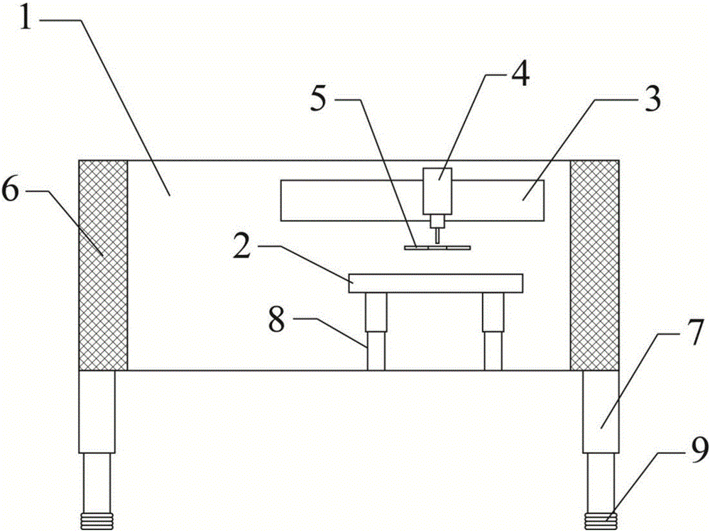
[0025] In the description of the present invention, unless otherwise specified, the orientation or state relationship indicated by the terms "upper", "lower", "top", "bottom", "longitudinal" etc. is based on the orientation or state relationship shown in the drawings , is only for the convenience of describing the present invention and simplifying the description, but does not indicate or imply that the mechanism or element referred to must have a specific orientation, be constructed and operated in a specific orientation, and thus should not be construed as limiting the present invention.

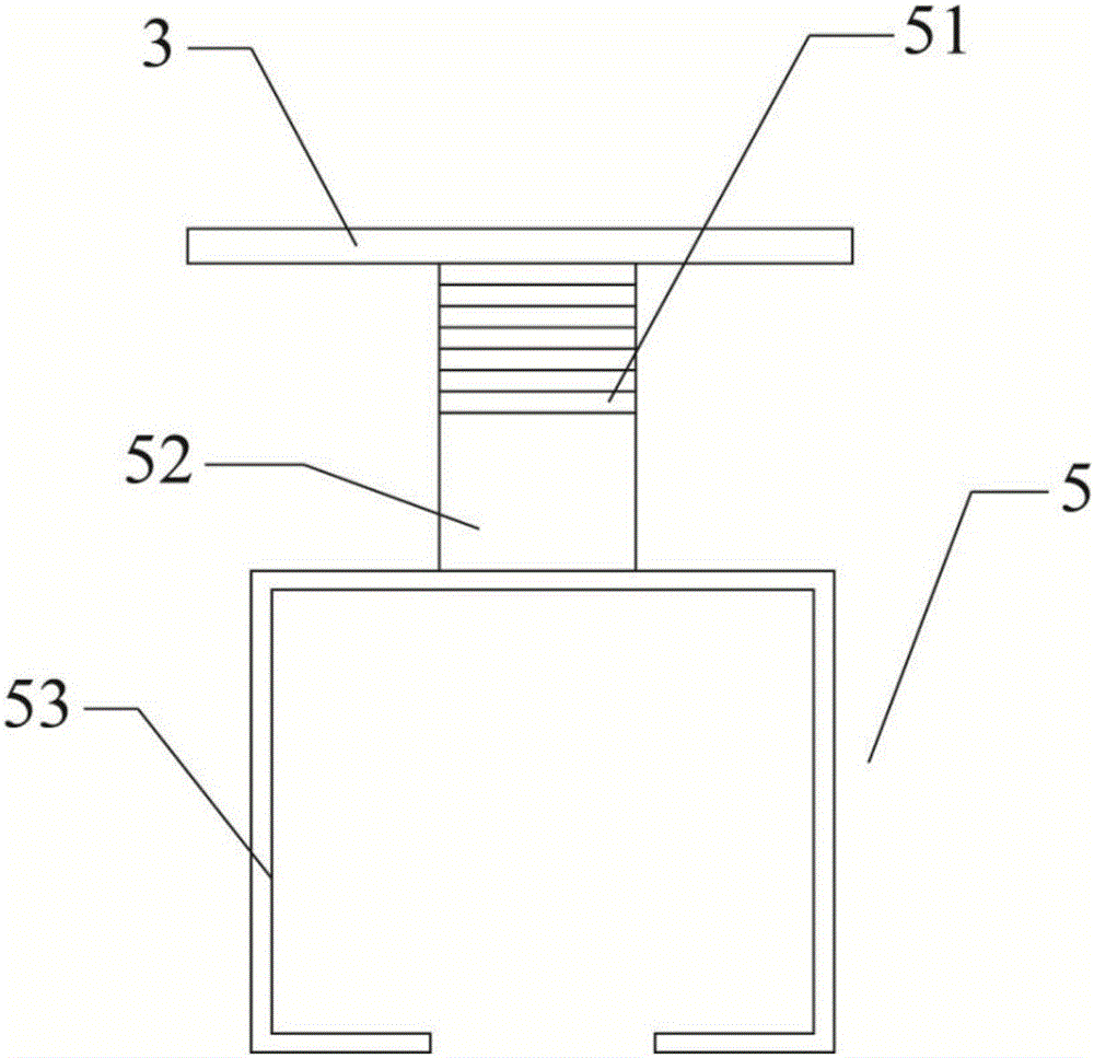
[0026] In the description of the present invention, it should be noted that unless otherwise specified and limited, the term "connection" should be understood in a broad sense, for example, it can be a fixed connection, a detachable connection, or an integral connection; directly or indirectly through an intermediary. Those of ordinary skill in the art can understand the specific meanings ...


PUM


Abstract

The invention provides a radio-frequency carving machine. The radio-frequency carving machine comprises a machine body, a workbench, a work frame and a carving machine head. The machine body is a cuboid cavity. The workbench, the work frame and the carving machine head are all arranged inside the machine body. The carving machine head is connected with the work frame. The carving machine head corresponds to the workbench in position. The radio-frequency carving machine is characterized in that purifying chambers are arranged on the two sides of the interior of the machine body, the bottom of the machine body is connected with machine body supporting columns, bottom feet are arranged at the bottoms of the machine body supporting columns, and two workbench supporting columns are arranged at the bottom of the workbench; the bottoms of the workbench supporting columns are fixed to an inner wall bottom plate of the machine body; the machine body supporting columns and the workbench supporting columns are each of a telescopic structure; and a clamping part is further arranged above the workbench, and one end of the clamping part stretches into the work frame. The purifying chambers are arranged in the machine body so that dust can be treated, and meanwhile the machine body supporting columns of the telescopic structure and the workbench supporting columns of the telescopic structure are arranged so that discharging can be convenient.

Description

technical field [0001] The invention belongs to the field of processing accessories, and relates to an engraving machine, in particular to a radio frequency engraving machine. Background technique [0002] In terms of processing principle, engraving is a combination of drilling and milling, which is divided into two types: laser engraving and mechanical engraving. The application range of the engraving machine is very wide. The low-power engraving machine is suitable for making two-color boards, architectural models, small signs, three-dimensional crafts, etc., because the power is too small, which greatly affects the scope of its application; high-power engraving machines can be used for low-power engraving machines. thing. Best for large cutting, embossing, engraving. [0003] Chinese patent ZL201520974224.2 provides a rotary engraving machine. There are aligners on both sides of the engraving head. The aligner is a photoelectric direct alignment device, which can help t...

Claims


Application Information

Patent Timeline
Patent Type & Authority Applications(China)
IPC IPC(8): B44B1/00B44B1/06B44B3/00B44B3/06B23K26/36
CPCB44B1/00B23K26/361B44B1/06B44B3/00B44B3/06B44B3/063
Inventor 刘明辉江勇朱秀梅
Owner TIANJIN HONGGUANG WEIYE LASER TECH CO LTD
Why Eureka
Try Eureka