Cooling and drying electrical cabinet convenient to move and position

A convenient moving and drying technology, applied in electrical components, substation/distribution device enclosures, substation/switch layout details, etc., can solve the problems of reduced service life of electrical components, influence of heat on internal electrical components, and difficulty in dissipating heat from electrical components. , to achieve the effect of fast operation, convenient movement and positioning, and lower temperature

Inactive Publication Date: 2016-06-29
金柯楠
View PDF5 Cites 47 Cited by
  • Summary
  • Abstract
  • Description
  • Claims
  • Application Information

AI Technical Summary

Problems solved by technology

[0003] In the prior art, when the power distribution cabinet is working, the internal electrical components themselves will generate heat, and the design of the power distribution cabinet is often sealed to ensure the safety of the electrical components, so the heat generated by the electrical components is often difficult to dissipate This part of the heat is very easy to affect the internal electrical components. In order to solve the above problems, the traditional power distribution cabinet will set up cooling holes at the bottom of the power distribution cabinet, or set up louvers on the side wall of the power distribution cabinet. Although this will Increase the heat dissipation efficiency inside the power distribution cabinet, but when the humi

Method used


Image

  • Cooling and drying electrical cabinet convenient to move and position

Examples


Embodiment Construction

[0014] The technical solution of this patent will be further described in detail below in conjunction with specific embodiments.

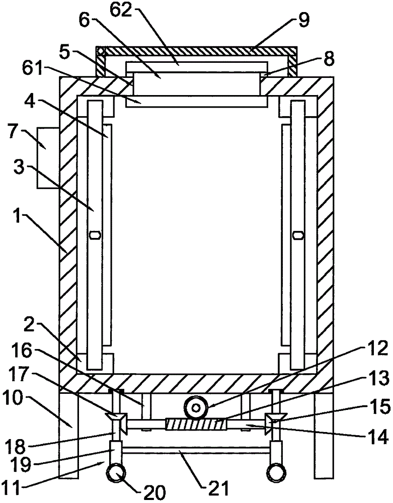
[0015] see figure 1 , a heat dissipation and drying electric cabinet that is convenient to move and locate, including a cabinet body 1, the left and right sides of the bottom and the left and right sides of the top of the cabinet body 1 are respectively provided with chute 2 along the front and rear directions, and the left and right sides of the cabinet body 1 , between the right side chute are respectively provided with a support plate 3, and the top and bottom ends of the support plate 3 are respectively slidably installed in the top and bottom chute 2 of the corresponding side, and the two support plates 3 are respectively provided with remote Infrared heating plate 4, the top of the cabinet body 1 is provided with an installation port 5, and a semiconductor refrigeration chip 6 is arranged in the installation port 5. The cold end 61 of the sem...


PUM


Abstract

The invention discloses a heat dissipation and drying electric cabinet which is convenient for movement and positioning, which comprises a cabinet body, a chute, a support plate, a far-infrared heating plate, and a semiconductor refrigeration sheet; A lifting mechanism fixed on the bottom of the cabinet is installed in the space of the cabinet. The lifting mechanism includes a worm wheel, a worm, a rotating shaft, a fixed rod, a driving bevel gear, a driven bevel gear, a screw, and a screw sleeve. Rollers are installed at the lower end of the screw sleeve. A connecting rod is installed between the sleeves. The invention is simple in structure, easy to use, strong in practicability, safe and reliable, reduces the influence of humidity on the high-voltage switch cabinet, and can effectively reduce the temperature inside the cabinet; by rotating the worm wheel, the contact between the roller and the bottom surface can be indirectly adjusted, so that the cabinet can be conveniently The body is moved and positioned, and the operation is fast and flexible.

Description

technical field [0001] The invention relates to electric equipment, in particular to a heat dissipation and drying electric cabinet which is convenient for movement and positioning. Background technique [0002] The electric cabinet is the power distribution cabinet. The power distribution cabinet (box) is divided into the power distribution cabinet (box), the lighting distribution cabinet (box), and the metering cabinet (box). It is the final equipment of the power distribution system. The power distribution cabinet is a general term for the motor control center. The power distribution cabinet is used in the occasions where the load is relatively scattered and there are few circuits; the motor control center is used in the occasions where the load is concentrated and there are many circuits. They distribute the electric energy of a certain circuit of the upper-level power distribution equipment to the nearest load. This level of equipment shall provide protection, monitor...

Claims


Application Information

Patent Timeline
IPC IPC(8): H02B1/28H02B1/56H02B1/52
CPCH02B1/28H02B1/52H02B1/565
Inventor 金柯楠
Owner 金柯楠
Why Eureka
Try Eureka