Magnetic bearing unit, and vacuum pump

A magnetic bearing and electromagnetic force technology, applied in the direction of bearings, axial flow pumps, shafts and bearings, etc., can solve the problems of increasing the memory capacity of control equipment and the need for a lot of time for initial adjustment, and achieve the effect of reducing memory capacity and suppressing vibration.

Active Publication Date: 2019-06-18
EDWARDS JAPAN
View PDF7 Cites 0 Cited by
  • Summary
  • Abstract
  • Description
  • Claims
  • Application Information

AI Technical Summary

Problems solved by technology

[0006] However, in the technology disclosed in the aforementioned Patent Document 1, a plurality of control coefficients obtained in advance are switched according to the installation direction of the vacuum pump (the rotating shaft of the magnetic bearing), and therefore it is necessary to store a large number of control coefficients in the control circuit.
Therefore, there is a possibility that the memory capacity of the control device becomes larger
In addition, initial adjustment of the relationship between the installation posture of the vacuum pump and the control coefficient of the current may take a lot of time.
Furthermore, in applications where the installation direction of the vacuum pump changes dynamically, the current fluctuates excessively at the moment of switching the control coefficient, so there is a possibility that vibrations will be generated in the magnetic bearing.

Method used


Image

  • Magnetic bearing unit, and vacuum pump
  • Magnetic bearing unit, and vacuum pump
  • Magnetic bearing unit, and vacuum pump

Examples


Embodiment

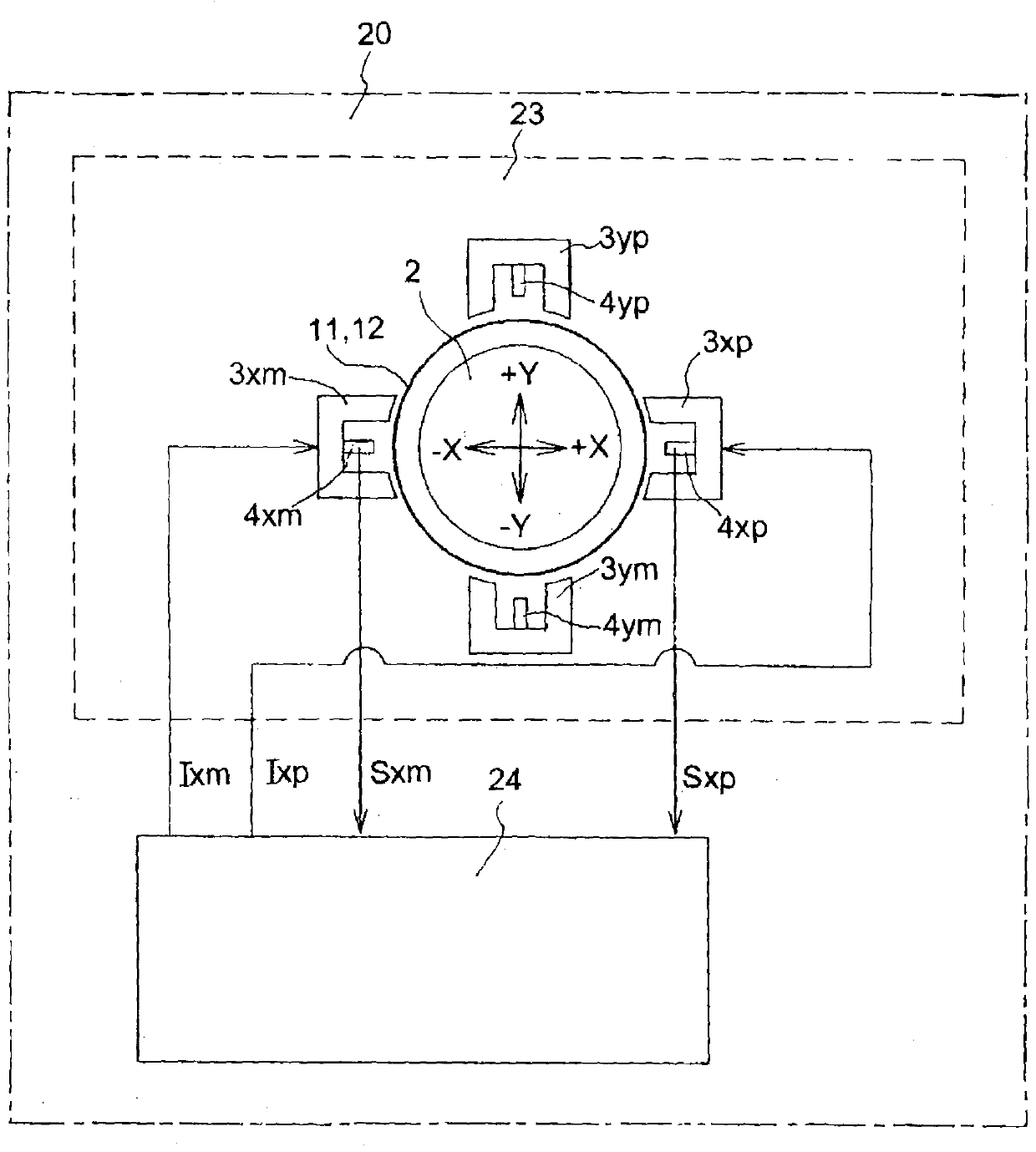
[0039] Below, refer to Figure 1 to Figure 5 Preferred embodiments of the magnetic bearing device according to the present invention will be described in detail. figure 1 It is a schematic configuration diagram of a 5-axis control type magnetic bearing applied to an embodiment of the present invention. This 5-axis control type magnetic bearing has a configuration in which control electromagnets and displacement sensors are arranged on four radial axes, and control electromagnets and displacement sensors are arranged on one axial axis. That is, this 5-axis control type magnetic bearing is configured to actively control 5 degrees of freedom except the degree of freedom around the rotation axis (translational motion of the center of gravity is 3 degrees of freedom, and rotational motion around the center of gravity is 2 degrees of freedom) exercise.

[0040] This 5-axis control type magnetic bearing is arranged in pairs (a pair) for the X-axis and the Y-axis in the radial direc...


PUM


Abstract

Provided is a magnetic bearing device which allows easy initial adjustment and allows optimal bearing control to be performed by a simple algorithm without increasing a memory capacity of a controller. A pair of square multipliers and an adder acquire respective steady-state current values of a pair of electromagnets which attract a rotor shaft of a magnetic bearing not shown in opposite radial directions, square the respective steady-state current values, and add up the respective squared steady-state current values. Then, to optimally change respective currents in the electromagnets in accordance with a mounting posture of the magnetic bearing, a correction coefficient arithmetic operator calculates a correction gain instruction value acting on the electromagnets from the steady-state current values squared / added up. Then, a gain instruction value obtained by adding the correction gain instruction value to a fundamental gain of a control circuit for the electromagnets is input to a gain amplifier. The gain amplifier generates a corrected current instruction value on the basis of the gain instruction value and optimally controls the magnetic bearing.

Description

technical field [0001] The present invention relates to a magnetic bearing device including a magnetic bearing that supports a rotating body in a non-contact manner by an electromagnetic force of an electromagnet, a control device for controlling the magnetic bearing, and a vacuum pump using the magnetic bearing device. Background technique [0002] Conventionally, magnetic bearings (5-axis control magnetic bearings) in which five degrees of freedom of six degrees of freedom of a rotating body (rigid body) are supported by the electromagnetic force (attractive force) of an electromagnet are widely known. This kind of magnetic bearing has the following excellent performance: because the bearing part is non-contact, so there is no wear and long life, because the bearing loss is small, it can be applied to ultra-high-speed rotating equipment, and the rigidity of the bearing can be adjusted arbitrarily, Damping characteristics, enabling low-vibration, low-noise rotation, etc. T...

Claims


Application Information

Patent Timeline
Patent Type & Authority Patents(China)
IPC IPC(8): F16C32/04F04D19/04
CPCF04D19/042F04D29/058F16C32/0451F16C32/0489F16C2231/00F16C2300/30F16C2360/45F04D29/048F04D27/00F04D29/053F16C2233/00F16C2360/00H02K7/09
Inventor 川岛敏明
Owner EDWARDS JAPAN
Why Eureka
Try Eureka