Machine needle cooling mechanism of sewing machine, sewing machine and air suction and exhaust mechanism

A cooling mechanism, sewing machine technology, applied in the direction of sewing machine components, sewing equipment, lubricating/cooling devices, etc., can solve the problems of increased injection volume, air introduction into the needle bar assembly, and inability to fully compress the air, etc.

Active Publication Date: 2016-07-06
BROTHER KOGYO KK
View PDF5 Cites 4 Cited by
  • Summary
  • Abstract
  • Description
  • Claims
  • Application Information

AI Technical Summary

Problems solved by technology

In the needle bar assembly described in the above publication, when the needle bar corresponding to the piston moves up and down at high speed, it is difficult for the spool to move up and down periodically following the up and down movement of the needle bar.
The needle bar assembly may not be able to introduce enough air into the interior to compress the air enough to increase the injection volume

Method used


Image

  • Machine needle cooling mechanism of sewing machine, sewing machine and air suction and exhaust mechanism
  • Machine needle cooling mechanism of sewing machine, sewing machine and air suction and exhaust mechanism
  • Machine needle cooling mechanism of sewing machine, sewing machine and air suction and exhaust mechanism

Examples


Embodiment Construction

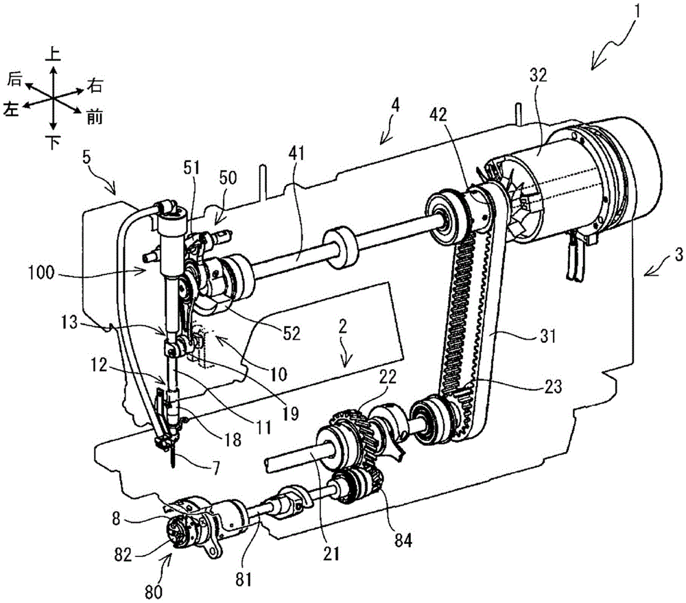
[0024] A schematic structure of a sewing machine 1 having a needle cooling mechanism will be described with reference to the drawings. In the following description, up and down, left and right, and front and back indicated by arrows in the figure are used. Such as figure 1 As shown, the sewing machine 1 includes a base portion 2 , a pillar portion 3 , an arm portion 4 and a top end portion 5 . The base portion 2 extends in the left-right direction, and has a lower shaft 21, a shuttle mechanism 80, and the like inside. The pillar part 3 extends upward from the right end side of the machine base part 2, and has a timing belt 31, a sewing machine motor 32, and the like inside. The arm part 4 extends leftward from the upper side of the pillar part 3 . The arm portion 4 faces the upper surface of the base portion 2 and has a spindle 41 and the like inside. The sewing machine motor 32 rotates the main shaft 41 clockwise when viewed from the left side. The arm part 4 has a tip p...


PUM


Abstract

The invention relates to a machine needle cooling mechanism of a sewing machine, a sewing machine and an air suction and exhaust mechanism, wherein the air injection amount can be increased. According to the technical scheme of the invention, a cover part is covered onto a cylinder part. A valve chamber is formed between the cover part and the upper end of the cylinder part. The cover part is provided with a suction port and an exhaust port. The valve chamber is communicated with the outside via the suction port and the exhaust port. A circular ring-shaped valve core with a circulation port at the center thereof is arranged in the valve chamber. The valve core is in a non-fixed state in the valve chamber and is capable of moving up and down. A piston is arranged at the upper end portion of a needle bar. The needle bar moves up and down to drive the piston to move downwards, and the external air enters the valve chamber via the suction port to push the valve core downwards. The air that enters the valve chamber flows into a pump chamber via the circulating port of the valve core. When the piston moves upwards, the piston compresses the air the pump chamber. The compressed air pushes the valve core and then the valve core blocks the suction port. The compressed air is injected to the outside via a pipeline through the circulating port and the exhaust port, so that the machine needle of the sewing machine can be cooled.

Description

technical field [0001] The invention relates to a sewing machine needle cooling mechanism, a sewing machine and an air suction and exhaust structure. Background technique [0002] The needle bar of the sewing machine moves up and down under the drive of the sewing machine motor. The needle bar is equipped with an organic needle at the lower end. The shuttle of the sewing machine rotates under the drive of the sewing machine motor. A bobbin wound with a bobbin thread is accommodated in the shuttle. The needle bar and the shuttle cooperate to interweave the upper thread supplied to the needle and the lower thread supplied by the bobbin to form stitches on the fabric. In industrial sewing machines, the needle bar moves up and down at high speed. Frictional heat is generated when the needle rubs against the fabric. When the temperature of the friction heat becomes high, the fabric may melt and the upper and lower threads may break. Some sewing machines have a needle coolin...

Claims


Application Information

Patent Timeline
Patent Type & Authority Applications(China)
IPC IPC(8): D05B71/04
CPCD05B71/04
Inventor 福岛将浩早川范一
Owner BROTHER KOGYO KK
Why Eureka
Try Eureka