Connecting structure of concrete-filled steel tube column and reinforced concrete beam

A technology for reinforced concrete beams and concrete-filled steel tubular columns, applied in the field of connection structures, can solve problems such as adverse construction efficiency and quality assurance, affecting building appearance and use space, and large welding workload, so as to improve the building appearance and use space, improve the The effect of connection stability and low welding workload

Active Publication Date: 2016-07-06
筑博设计股份有限公司
View PDF5 Cites 11 Cited by
  • Summary
  • Abstract
  • Description
  • Claims
  • Application Information

AI Technical Summary

Problems solved by technology

At present, the connection method between steel pipe concrete columns and reinforced concrete beams is generally fixed by welding the ring-shaped steel plate welded on the outer surface of the steel pipe and the steel bars of the reinforced concrete. All steel bars need to be welded on the ring steel plate so that they can be connected and fixed firmly enough
However, the welding workload of the above-mentioned connection method is very large, and the requirements for welding quality are also high, so it is not conducive to construction efficiency and quality assurance

Method used


Image

  • Connecting structure of concrete-filled steel tube column and reinforced concrete beam
  • Connecting structure of concrete-filled steel tube column and reinforced concrete beam
  • Connecting structure of concrete-filled steel tube column and reinforced concrete beam

Examples


Embodiment Construction

[0023] The present invention will be further described below in conjunction with the accompanying drawings and specific embodiments.

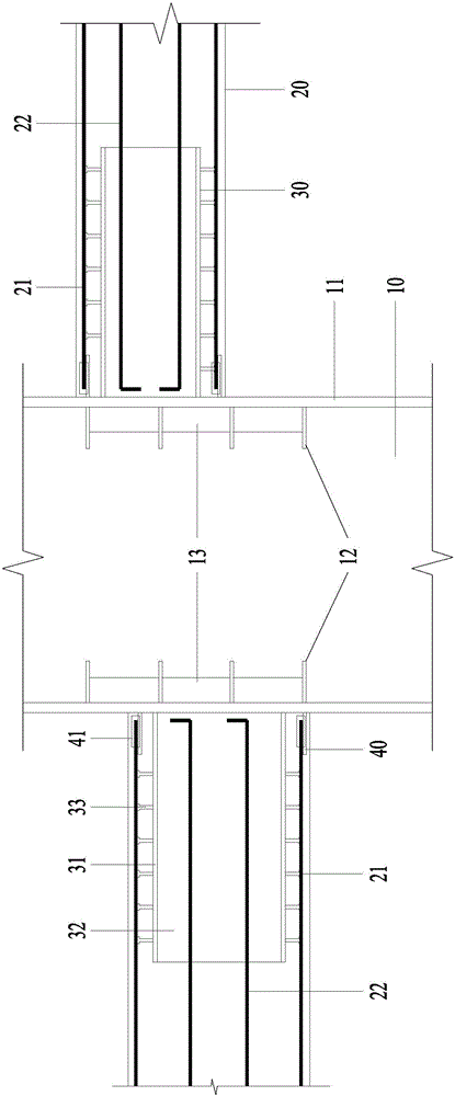
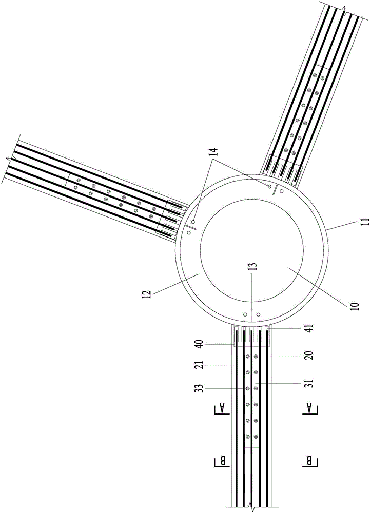
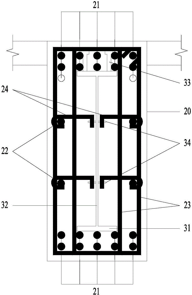
[0024] See Figure 1 to Figure 4 , a connection structure between a steel tube concrete column and a reinforced concrete beam designed in a preferred embodiment of the present invention, comprising: a steel tube concrete column 10 and a plurality of steel tube concrete beams 20 of different elevations connected to the steel tube concrete column 10 .

[0025] The concrete filled steel pipe column 10 is composed of a steel pipe 11 and concrete poured in the steel pipe 11 . A plurality of circumferential stiffening plates 12 arranged at intervals are arranged on the inner surface of the steel pipe 11, and longitudinal stiffening ribs 13 are vertically arranged between the circumferential stiffening plates 12, and the longitudinal stiffening ribs 13 are also connected to the inner surface of the steel pipe 11. A plurality of ventilation holes 14 a...


PUM


Abstract

The invention discloses a connecting structure of a concrete-filled steel tube column and a reinforced concrete beam. The connecting structure comprises the concrete-filled steel tube column made of a steel tube and concrete and the reinforced concrete beam made of a reinforcing steel bar and concrete; a boom extending steel beam is welded on the outer side surface of the steel tube and consists of flanges and a web plate; pull and tie plates parallel to the flanges are symmetrically welded on the two sides of the web plate; bar penetration holes are formed in the pull and tie plates; the reinforcing steel bar comprises longitudinal bars arranged on the upper side and the lower side, lumbar bars arranged on the left side and the right side, a first stirrup connected onto the longitudinal bars and the lumbar bars in a bundling manner and a pull and tie bar with two ends respectively colluded on the crossed lumbar bars and the first stirrup; one end of the reinforced concrete beam is inserted into the boom extending steel beam; the pull and tie bar is cut into two sections by the web plate of the boom extending steel beam, and the cut ends of the pull and tie bar are inserted into the bar penetration holes. Through the overlap joint of the reinforcing steel bar and the boom extending steel beam, the anchorage and the force transmission of the reinforcing steel bar are realized. The connecting structure disclosed by the invention has the advantages of being strong in bending and shear bearing capacity, small in welding workload, simple in mounting process and convenient and quick to construct.

Description

technical field [0001] The invention relates to a connection structure between a steel pipe concrete column and a reinforced concrete beam with different elevations, and belongs to the technical field of building structure engineering. Background technique [0002] Concrete-filled steel pipe columns are composed of steel pipes and concrete, and their structural characteristics are steel pipes on the outside and poured concrete on the inside. Due to its good working performance and easy construction, CFST columns have been widely used in high-rise buildings, bridge engineering, underground engineering and other industries, and have achieved good architectural effects and economic benefits. In high-rise buildings or underground projects, the frame columns mainly use steel pipe concrete columns, and the frame beams use the corresponding reinforced concrete beams. At present, the connection method between steel pipe concrete columns and reinforced concrete beams is generally fi...

Claims


Application Information

Patent Timeline
Patent Type & Authority Applications(China)
IPC IPC(8): E04B1/21E04B1/58
CPCE04B1/215E04B1/58
Inventor 张梅松马镇炎王锦文王洪欣
Owner 筑博设计股份有限公司
Why Eureka
Try Eureka