Casing pipe device structure used for oil drilling and capable of preventing casing damage due to fault slippage

A casing device and oil drilling technology, which is applied in the direction of drilling pipes, casings, drilling equipment, etc., can solve problems such as limited shear stress, achieve easy installation and practical application, reduce requirements, and achieve obvious effects

Active Publication Date: 2016-07-06
LIAONING UNIVERSITY OF PETROLEUM AND CHEMICAL TECHNOLOGY
View PDF7 Cites 9 Cited by
  • Summary
  • Abstract
  • Description
  • Claims
  • Application Information

AI Technical Summary

Problems solved by technology

[0008] The current preventive measures for casing damage caused by fault slippage are limited to casing material selection, without structural improvement. The present invention provides a casing device structure for oil drilling to prevent casing damage caused by fault slippage , in order to solve the problem that the existing materials have limited effect on the strong shear stress generated by the fault slip of the casing, and reduce the incidence of casing damage caused by fault slip

Method used


Image

  • Casing pipe device structure used for oil drilling and capable of preventing casing damage due to fault slippage
  • Casing pipe device structure used for oil drilling and capable of preventing casing damage due to fault slippage
  • Casing pipe device structure used for oil drilling and capable of preventing casing damage due to fault slippage

Examples


Embodiment Construction

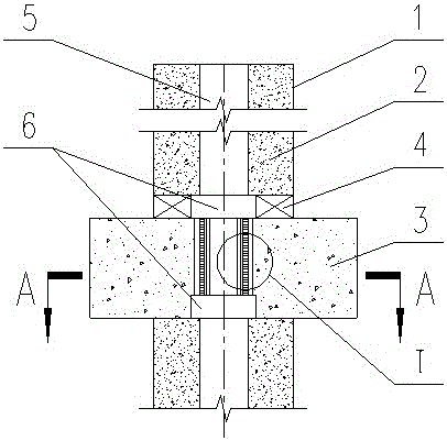
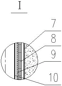
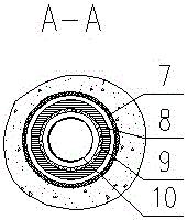
[0023] In the inner layer and the outer layer of steel wire mesh in the embodiment of the present invention, the pores formed by the interweaving of warp and weft threads can be square, rectangular, diamond-shaped, or honeycomb, and the mesh number is not limited. The higher the mesh number, the better the effect .

[0024] The rigid and movable casing structure in the embodiment of the present invention can be a spiral coil of steel bars or a laminated steel coil with internal tension bars. The number of coils and coils is not limited and can be determined according to the actual situation of the fault.

[0025] In the rigid and movable casing structure in the embodiment of the present invention, the cross-sectional short surface of the stacked steel ring of the spiral coil group of steel bars or the internal tie bars can be square, rectangular, perfect circle, trapezoidal, rhombus and Oval and other shapes.

[0026] Embodiments of the invention:

[0027] A casing device us...


PUM


Abstract

The invention discloses a casing pipe device structure used for oil drilling and capable of preventing casing damage due to fault slippage. The casing pipe device structure is installed in the expanding section of a fault and mainly composed of a movable joint of a four-layer structure. A rigidity followable casing pipe layer of the movable joint is connected with an upstream casing pipe part and a downstream casing pipe part through threaded connecting parts. The four-layer structure of the movable joint is connected into a whole at the two ends of the movable joint. An outer steel wire knitmesh is arranged on the outer side of the rigidity followable casing pipe layer, and an inner steel wire knitmesh and a flexible hose are sequentially and inwards arranged in the rigidity followable casing pipe layer. In the fault zone, displacement caused by fault slippage can be offset by a buffer space between the outer steel wire knitmesh of the movable joint and the stratum, the transverse displacement deformation and confining capacity of the rigidity followable casing pipe layer of the movable joint and a ring-pillar-shaped gap between the inner steel wire knitmesh and the flexible hose in the innermost layer. Meanwhile, mud or sandy soil can be effectively prevented from entering the flexible hose in the innermost layer through the outer steel wire knitmesh and the inner steel wire knitmesh, and the flexible hose can properly deform along with partial displacement deformation of the rigidity followable casing pipe layer, so that the flexible hose does not crack and influence oil recovery operation.

Description

technical field [0001] The invention relates to a casing device structure for oil drilling to prevent casing damage caused by fault slippage, which is characterized in that a movable joint with a four-layer structure is installed in the fault reaming section to prevent casing damage caused by fault slippage , belonging to the field of petroleum engineering technology. Background technique [0002] In an oil well, the casing is a steel pipe used to protect the oil suction pipe on the outer layer of the oil pumping pipe, and the outermost layer of the entire oil pumping system is in direct contact with the oil or the formation. During oil field production, when factors such as engineering, geology, and production dynamics change the load on the casing that exceeds the bearing capacity of the casing, the casing will be deformed, broken, and broken, that is, casing damage, referred to as casing damage. [0003] Casing damage is a common problem in major oil fields at home and ...

Claims


Application Information

Patent Timeline
Patent Type & Authority Applications(China)
IPC IPC(8): E21B17/08E21B17/10B32B15/02B32B1/08
CPCB32B1/08B32B15/02B32B2262/103B32B2597/00E21B17/08E21B17/1078
Inventor 李剑虹王卫强吴明多依丽海军
Owner LIAONING UNIVERSITY OF PETROLEUM AND CHEMICAL TECHNOLOGY
Why Eureka
Try Eureka