Mixer for an exhaust gas duct system of an internal combustion engine

A technology of mixing device and exhaust gas guidance, which is applied in the direction of exhaust device, internal combustion piston engine, mixer, etc., can solve the problem of internal combustion engine power reduction and achieve the effect of compact structure

Inactive Publication Date: 2016-07-06
EBERSPACHER EXHAUST TECH GMBH & CO KG
View PDF9 Cites 1 Cited by
  • Summary
  • Abstract
  • Description
  • Claims
  • Application Information

AI Technical Summary

Problems solved by technology

But the problem here is that the integration of mixing elements into the exhaust gas flow increases the exhaust gas counterpressure due to the flow resistance created by such mixing elements, which leads to a reduction in the power of the internal combustion engine

Method used


Image

  • Mixer for an exhaust gas duct system of an internal combustion engine
  • Mixer for an exhaust gas duct system of an internal combustion engine
  • Mixer for an exhaust gas duct system of an internal combustion engine

Examples


Embodiment Construction

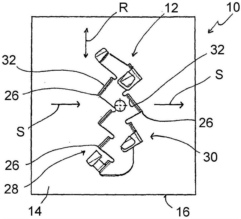
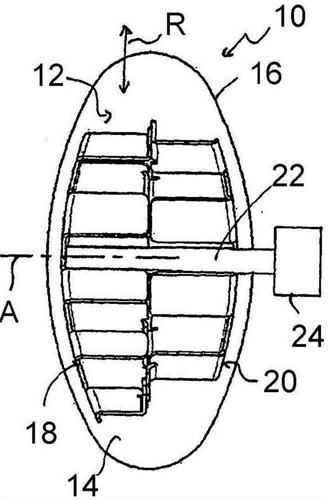
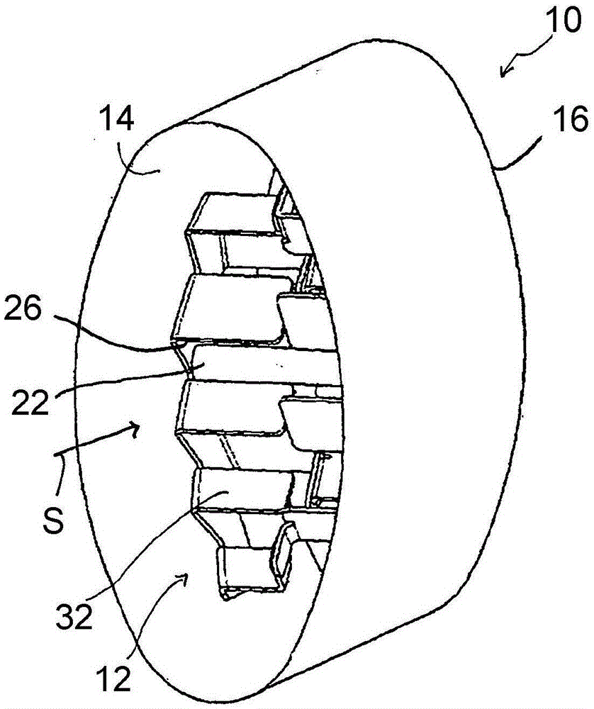
[0037] Refer below Figures 1 to 7 A first embodiment of a mixing device 10 for an exhaust gas guidance system is described. here, Figure 1 to Figure 4 A first operating state of the mixing elements of the mixing device 10 , designated overall by 12 , is shown, in which the mixing device 10 generates and introduces into the exhaust gas necessary for the flow in the flow channel 14 in the main flow direction S The maximum mixing effect of additives. In this case, the flow channel 14 is formed in a tubular flow channel element 16 . Figures 5 to 7 The mixing device 10 is shown with the mixing element 12 positioned in the second operating state with a minimal mixing effect of the mixing device 10 .

[0038] exist Figures 1 to 7 In the embodiment of the mixing device 10 shown in , a tubular flow channel element 16 is shown which provides an approximately elliptical flow cross-section for the exhaust gas or additive flowing generally in the main flow direction S. It should b...


PUM


Abstract

A mixer for an exhaust gas duct system of an internal combustion engine includes a flow channel element (16) with a flow channel (14), through which exhaust gases can flow in a main direction of flow (S). At least one mixer element (12) in the flow channel element (16) is movable in the flow channel element (16) to change a mixing effect.

Description

technical field [0001] The invention relates to a mixing device for an exhaust gas guidance system of an internal combustion engine. Exhaust gas guidance systems of this type generally comprise flow channels in the flow channel element through which exhaust gas can flow in the main flow direction. Such a flow channel can lead from an internal combustion engine, for example a diesel internal combustion engine, to the catalytic converter device and thus further to the surroundings. Background technique [0002] In order to be able to meet ever more stringent requirements regarding the emission of pollutants from internal combustion engines, in particular diesel internal combustion engines, it is known to introduce additives, such as urea, into the exhaust gas flow downstream of the internal combustion engine. In order to achieve the greatest possible effect, this additive needs to be mixed efficiently with the exhaust gas. The problem here, however, is that the integration o...

Claims


Application Information

Patent Timeline
Patent Type & Authority Applications(China)
IPC IPC(8): F01N3/28
CPCF01N3/28F01N3/2066F01N3/2892F01N13/00F01N2240/20F01N2290/00F01N2450/30F01N2610/02Y02T10/12B01F25/4311B01F25/4316B01F25/431973B01F25/431974B01F25/43161F01N13/08
Inventor S·卡尔沃E·库尔佩约维克O·塞梅诺夫D·宾德尔M·伯格勒S·格拉泽M·伊林G·法伊尔-纳赖恩R·赫尔施J·黑尼施S·瓦雷里斯
Owner EBERSPACHER EXHAUST TECH GMBH & CO KG
Why Eureka
Try Eureka