
Aviation diesel engine piston combustion chamber and combustion system

A combustion system and combustion chamber technology, applied to pistons, mechanical equipment, engine components, etc., can solve the problems of prolonging fuel injection time, affecting aviation flight mileage, increasing fuel consumption rate, etc., achieving low engine weight requirements and avoiding severe fuel consumption Hit the wall and burn efficiently

Inactive Publication Date: 2016-07-06
CHERY AUTOMOBILE CO LTD
View PDF6 Cites 7 Cited by
  • Summary
  • Abstract
  • Description
  • Claims
  • Application Information

AI Technical Summary

Problems solved by technology

[0004] Due to the pursuit of power-to-weight ratio of small aviation diesel engines, at high speeds such as 3500-4000r / min, the fuel injection time measured by the crank angle is significantly prolonged, and the fuel injection duration is above 35°CA; in order to reduce the quality of the diesel engine and limit the maximum explosion pressure, As a result, the fuel injection advance angle is limited, which causes the aviation diesel engine to still inject a large amount of fuel at 15°CA after it is launched. At this time, the piston has obviously moved downward. The upper side wall of the piston and the top surface of the clearance piston will increase the effective fuel consumption rate, which in turn will affect the flight mileage

Method used


Image

  • Aviation diesel engine piston combustion chamber and combustion system
  • Aviation diesel engine piston combustion chamber and combustion system
  • Aviation diesel engine piston combustion chamber and combustion system

Examples


Embodiment Construction

[0025] The specific implementation manner of the present invention will be described in further detail below by describing the embodiments with reference to the accompanying drawings.

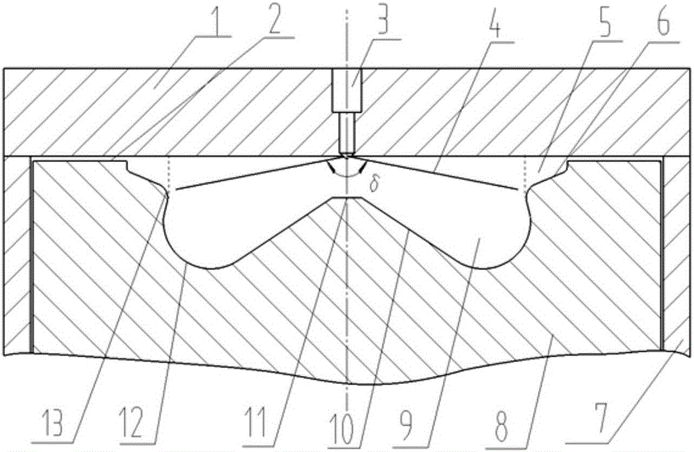
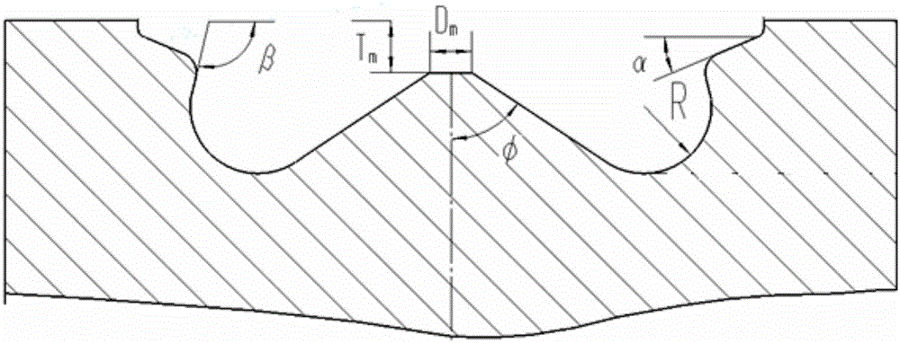
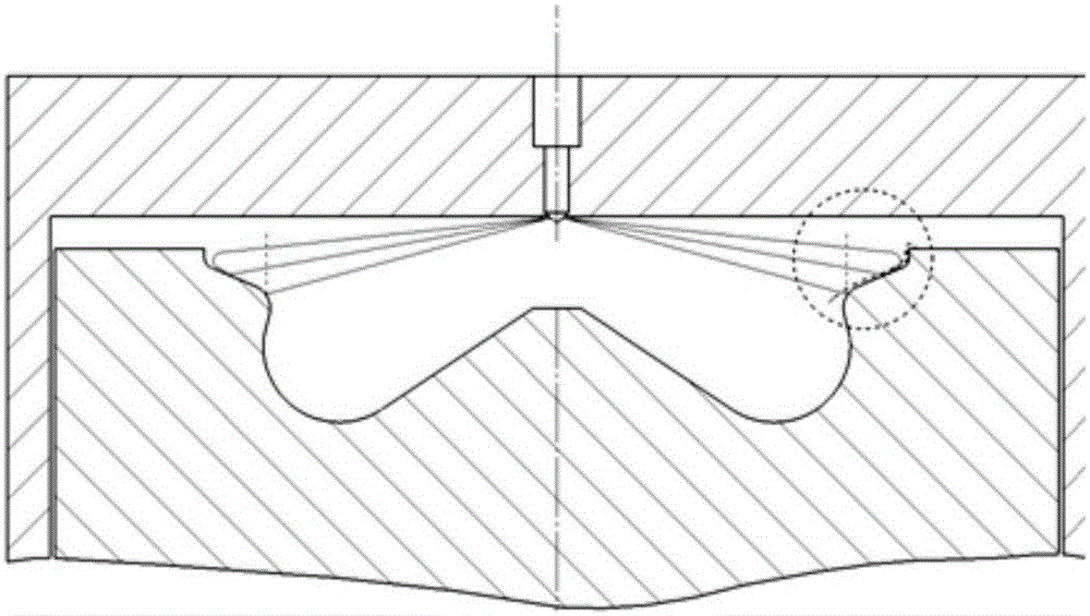
[0026] Such as Figure 1 to Figure 5 As shown, the piston combustion chamber and the combustion system of the aviation diesel engine include a cylinder head 1 and a cylinder barrel 7, a piston 8 is arranged in the cylinder barrel 7, a cavity of the combustion chamber is formed between the top of the piston and the cylinder head, and a combustion chamber is arranged on the top of the piston. Chamber pit 9, the top of the piston on the edge of the combustion chamber is provided with a groove 5, the groove is located outside the pit of the combustion chamber, and the cylinder head 1 is provided with an injector 3.

[0027] The combustion chamber pit 9 is located at the piston head, and the combustion chamber pit is an ω-shaped pit. The entire combustion chamber pit is symmetrical about the piston ...


PUM

PropertyMeasurementUnit
Diameteraaaaaaaaaa
Diameteraaaaaaaaaa

Abstract

The invention discloses an aviation diesel engine piston combustion chamber and a combustion system. The aviation diesel engine piston combustion chamber comprises a cylinder cover and a cylinder barrel, wherein a piston is arranged in the cylinder barrel; a cavity of the combustion chamber is formed between the top of the piston and the cylinder cover; a combustion chamber concave pit is formed in the top of the piston; a groove is formed in the top of the piston and is located around the combustion chamber; and the groove is located on the outer side of the combustion chamber pit. The requirements of high power per liter, relatively low explosion pressure, engine weight and low effective brake specific fuel consumption during high-speed high-load operation of an aviation diesel engine can be met.

Description

technical field [0001] The invention relates to the technical field of engines, in particular to a piston combustion chamber and a combustion system of an aviation diesel engine. Background technique [0002] With the announcement of the country's "Opinions on Deepening the Reform of the Low-altitude Airspace Management System" and "Regulations on the Approval and Management of General Aviation Aviation Flight Missions", the scale of the domestic general aviation industry has gradually formed. An important strategic opportunity, vigorously develop the entire industry chain of general aviation, and cultivate and expand the airport industry. Among them, aero-engine, one of the core industries of general aviation, has also received increasing attention. [0003] At present, most of the small aviation piston engines are gasoline engines, and the research and development of small aviation heavy oil piston engines is only in the demonstration stage; while foreign countries have a...

Claims


Application Information

Patent Timeline
IPC IPC(8): F02F3/26
CPCF02F3/26
Inventor 胡鹏刘义克刘华龙王伟
Owner CHERY AUTOMOBILE CO LTD
Learn More