Combined cycle engine

A technology of engine and detonation engine, which is applied in the direction of engine components, machines/engines, mechanical equipment, etc., can solve problems such as thrust cannot meet the requirements, poor economy, wide working envelope, etc., to improve economy and reliability, solve Combustion instability, thermal efficiency improvement effect

Active Publication Date: 2016-07-06
清航空天(浙江)科技有限公司
View PDF6 Cites 13 Cited by
  • Summary
  • Abstract
  • Description
  • Claims
  • Application Information

AI Technical Summary

Problems solved by technology

However, this type of aircraft has the characteristics of wide working envelope and complex and changeable flight conditions. It is difficult for a single type of propulsion device to complete all the work requirements independently. Therefore, combined power technology emerged as the times require and quickly attracted people's attention
The two types of combined cycle engines that are currently being studied are the rocket ramjet combined cycle engine and the turbo ramjet combined cycle engine. The former is not economical because it does not effectively use the oxygen in the atmosphere, and it is currently difficult to meet the requirements of repeated use. For the latter, The biggest problem is the mode conversion. The maximum operating Mach number of the turbine engine is lower than the effective starting Mach number of the ramjet engine, so that when the combined engine switches from the turbine mode to the ramjet mode, the thrust cannot meet the requirements.

Method used


Image

  • Combined cycle engine
  • Combined cycle engine
  • Combined cycle engine

Examples


Embodiment Construction

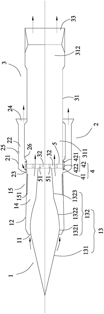
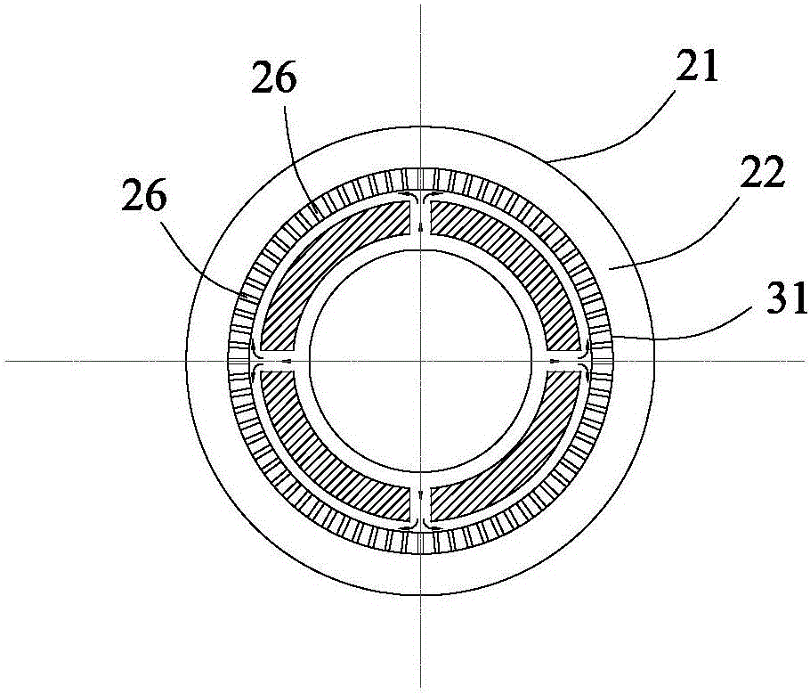
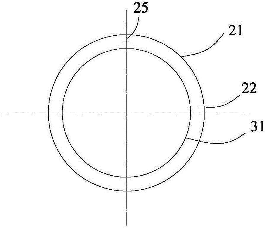
[0031] The combined cycle engine according to the present invention will be described in detail below with reference to the accompanying drawings.

[0032] refer to Figure 1 to Figure 6 , according to the combined cycle engine of the present invention, comprising: a supersonic air intake mechanism 1, which has a first gas inlet 11 open in the axial direction communicated with the outside; a continuously rotating detonation engine 2, which is fixedly connected to the supersonic air intake mechanism 1 Downstream; And turbojet engine 3, is fixedly connected to the downstream of supersonic air intake mechanism 1. Wherein, both the continuously rotating detonation engine 2 and the turbojet engine 3 are in controlled communication with the supersonic air intake mechanism 1 so as to controlly introduce external air through the first gas inlet 11 to work.

[0033] In the combined cycle engine according to the present invention, both the continuously rotating detonation engine 2 and ...


PUM


Abstract

The invention provides a combined cycle engine. The combined cycle engine comprises a supersonic air inlet mechanism, a continuous rotation detonation engine body and a turbojet engine body, wherein the supersonic air inlet mechanism is provided with a first gas inlet which communicates with the outside and is opened in the axial direction, and the continuous rotation detonation engine body and the turbojet engine body are fixedly connected to the lower portion of the supersonic air inlet mechanism. The continuous rotation detonation engine body and the turbojet engine body both communicate with the supersonic air inlet mechanism in a controlled mode in order to work in the mode that external gas is introduced into the continuous rotation detonation engine body and the turbojet engine body through the first gas inlet in the controlled mode. According to the combined cycle engine, mode transition can be completed within an operating envelope range, the stable thrust is provided for an aircraft, and then the aircraft hypersonically flies at 5.0 Mach or above in the atmosphere and can land and take off horizontally; in addition, the specific impulse of the engine is improved on the basis of adopting the continuous rotation detonation technique, the combustion heat efficiency is improved, and the economy and the reliability of the engine are improved.

Description

technical field [0001] The invention relates to the technical field of aerospace power, in particular to a combined cycle engine. Background technique [0002] Near-space hypersonic vehicles with a maximum flight speed of around Mach 5.0 have advantages such as superior high-altitude and high-speed characteristics, flexible maneuverability, and high penetration probability, and have very important potential military value. In addition, with the advancement of missile defense technology, the penetration and survivability of traditional missiles are also greatly threatened, and there is an urgent need to improve mobility through high-speed propulsion devices. However, this type of aircraft has the characteristics of wide working envelope and complex and changeable flight conditions. It is difficult for a single type of propulsion device to complete all the work requirements independently. Therefore, combined power technology emerged as the times require and quickly attracted p...

Claims


Application Information

Patent Timeline
Patent Type & Authority Applications(China)
IPC IPC(8): F02K7/00F02C7/04F02C7/057
CPCF02C7/04F02C7/057F02K7/00
Inventor 计自飞王兵谢峤峰张会强
Owner 清航空天(浙江)科技有限公司
Why Eureka
Try Eureka