Pressure adjustable reciprocating synchronization alternating current and direct current electromagnetic pump

A reciprocating and synchronous handover technology, applied in the field of electromagnetic pumps, can solve problems such as energy loss, inability to adjust, and energy waste, and achieve good social and economic benefits, automatic adjustment of output pressure, and novel and unique structures

Inactive Publication Date: 2016-07-06
HENAN INST OF ENG
View PDF4 Cites 0 Cited by
  • Summary
  • Abstract
  • Description
  • Claims
  • Application Information

AI Technical Summary

Problems solved by technology

Conventional electromagnetic pumps often use half-width push in order to match the rotor and stator poles, that is, two round trips in one working cycle of the piston, one push and one suction, which makes the continuity of fluid delivery worse and increases the pump efficiency. The discount brings great difficulty and cost to the installation, use and operation of the electromagnetic pump, and also causes a lot of energy loss
Moreover, the traditional delivery pumps have fixed heads and flow rates, and cannot set or adjust delivery parameters according to actual working conditions, nor can they adjust themselves according to changes in fluid flow conditions in the actual working environment, resulting in large pressure fluctuations or idling, which brings great harm to the project. Brings a lot of difficulties and waste of energy in the application
In addition, mechanical pumps often produce air binding or cavitation due to flow changes, causing damage to the pump body or even accidents. Therefore, the existing technology is in urgent need of improvement and development

Method used


Image

  • Pressure adjustable reciprocating synchronization alternating current and direct current electromagnetic pump

Examples


Embodiment Construction

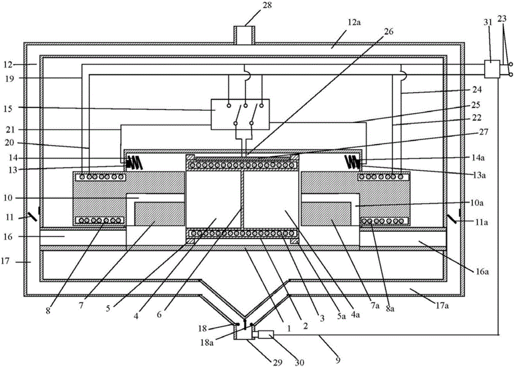
[0010] The specific implementation manners of the present invention will be described in further detail below in conjunction with the accompanying drawings.

[0011] Depend on figure 1 Given, the present invention comprises pump body, pipeline part and control part, and pump body 1 is cylindrical hollow structure, and pump body 1 two ends are fixed with the first electromagnetic column 7 and the second electromagnetic column 7a that are arranged symmetrically opposite, the first electromagnetic column Both the post 7 and the second electromagnetic post 7a are half placed outside the pump body, and half are placed inside the pump body. The first electromagnetic post and the second electromagnetic post on the external part of the pump body are respectively wound with a first electromagnetic coil 8 and a second electromagnetic post. The coil 8a, between the first electromagnetic column and the second electromagnetic column, is provided with an electromagnetic plug tube 2 sliding ...


PUM


Abstract

The invention relates to a pressure adjustable reciprocating synchronization alternating current and direct current electromagnetic pump. According to the technical scheme of the invention, the electromagnetic pump comprises a pump body, a pipeline portion and a control portion, wherein the pump body is of a cylindrical and hollow structure. A first electromagnetic column and a second electromagnetic column, arranged in symmetry and right opposite to each other, are fixed to the two ends of the pump body. An electromagnetic plug cylinder sliding in the length direction of an inner cavity of the pump body is arranged in the pump body and located between the first electromagnetic column and the second electromagnetic column. The pipeline portion comprises a first suction pipe, a second suction pipe, a first exhaust pipe and a second exhaust pipe. The first suction pipe and the second suction pipe intersect at a fluid inlet while the first exhaust pipe and the second exhaust pipe intersect at a fluid outlet. The control portion comprises a controller, a double pole double throw electromagnetic relay and a pressure sensor. The pressure adjustable reciprocating synchronization alternating current and direct current electromagnetic pump is efficient and saves energy, the output pressure can be adjusted automatically, and both alternating current and direct current can be used. Common problems, bothering fluid conveying equipment, such as idling, air bind and gas etching need not to be considered, the safe fluid conveying can be achieved, operation is simple, and the service life is long.

Description

technical field [0001] The invention relates to an electromagnetic pump, in particular to a reciprocating synchronous AC and DC electromagnetic pump with adjustable pressure. Background technique [0002] Electromagnetic pump is a power pump used to transport corrosive, dangerous liquid or liquid metal in chemical industry, printing and dyeing industry. It generates magnetic field through electromagnetic coil, and uses electromagnetic force to make the piston move in the pump body, thereby generating driving force, so that fluid flow. Electromagnetic pumps usually include pump body, rotor, stator and lines. Conventional electromagnetic pumps often use half-width push in order to match the rotor and stator poles, that is, two round trips in one working cycle of the piston, one push and one suction, which makes the continuity of fluid delivery worse and increases the pump efficiency. The discount brings great difficulty and cost to the installation, use and operation of the ...

Claims


Application Information

Patent Timeline
Patent Type & Authority Applications(China)
IPC IPC(8): F04B17/04F04B49/06
CPCF04B17/04F04B49/06
Inventor 谷保祥刘帅霞王喜英刘碧波
Owner HENAN INST OF ENG
Why Eureka
Try Eureka