
A swirler and a premix burner using it

A technology of premixed combustion and cyclone, which is applied in the direction of combustion chamber, combustion method, combustion equipment, etc., can solve the problems of increasing local high temperature area, boundary layer tempering, increasing the gas flow rate of premixing channel, etc., so as to avoid tempering And hang the fire, power adjustment is convenient, the effect of stable combustion

Active Publication Date: 2018-11-06
INNER MONGOLIA ZHONGKE PUSHI GAS TURBINE CO LTD
View PDF8 Cites 0 Cited by
  • Summary
  • Abstract
  • Description
  • Claims
  • Application Information

AI Technical Summary

Problems solved by technology

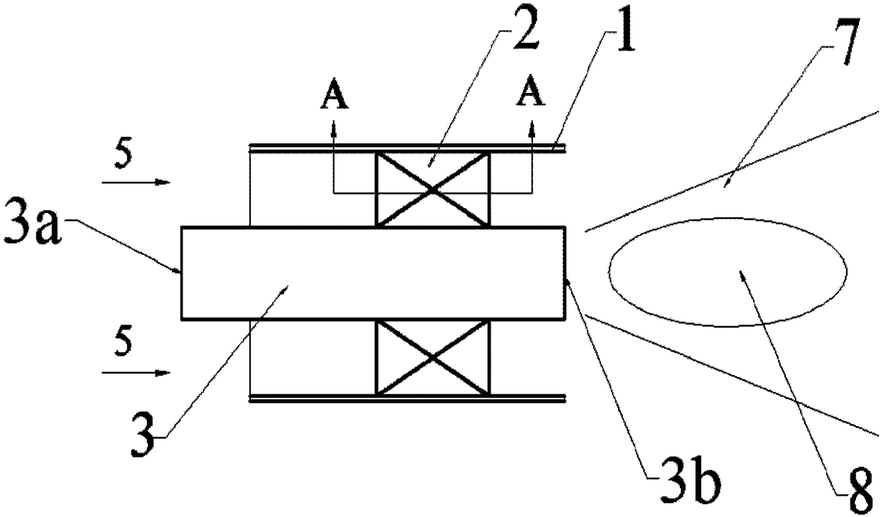
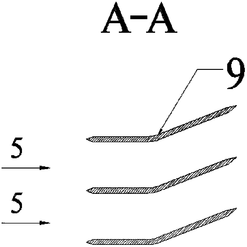
This is a major problem faced by premixed combustion. The usual solutions and adverse effects are: (1) retain a small amount of fuel injection on the end face 3b of the center body to form a diffusion flame and keep the flame stable, but it will increase the local high temperature area, Not conducive to reducing NO X ; (2) increase the gas flow rate in the premixing channel to prevent the flame from propagating upstream, but it will not eliminate the formation of low-velocity zones or even backflow vortices at the back of the swirl blades, and these zones will still become the stagnant zones of the flame after tempering; (3) Increase the distance between the trailing edge of the blade 9 of the swirler 2 and the end face 3b of the central body, but this will increase the length of the burner and may induce boundary layer tempering

Method used


Image

  • A swirler and a premix burner using it
  • A swirler and a premix burner using it
  • A swirler and a premix burner using it

Examples


Embodiment 1

[0039] This embodiment describes the application of the present invention in combination with the working process of the gas turbine, see Figure 6 . A gas turbine generally includes a compressor 31 , a combustion chamber 32 , a turbine 33 , and a load 35 (such as a generator) and the like. The air 30 is compressed by the compressor 31 to form a high-pressure gas 37, and then enters the combustion chamber 32 to be mixed with fuel to form a high-temperature and high-pressure flue gas 38. The flue gas 38 drives the turbine 33 to rotate to do work and drives the compressor 31 and the load 35 to rotate, and is output to the outside power or electricity.

[0040] The fuel supply pipeline 36 of the combustion chamber 32 of the gas turbine should be provided with corresponding valves and branches according to the needs of the burner. The fuel pipeline applying the burner of the present invention must include at least two types of branches: the diffusion fuel pipeline 36a and the pr...

Embodiment 2

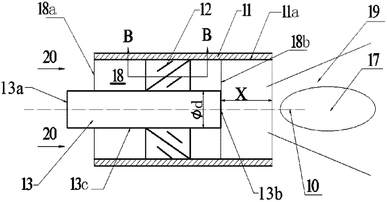
[0044] The novel burner of the present invention can also be applied to gas or oil-fired boilers, see Figure 7 . In the case of using fuel oil, there needs to be a heating device that heats the fuel oil to evaporate it into vapor. After the fuel oil is evaporated into a gaseous state, its application is similar to that of gaseous fuel, so the application for gas described later is the same Can be used for fuel. The gas boiler includes a boiler body 44, a blower 41, a burner 43, a fuel pipeline 46, and the like. After the air 30 is pressurized by the blower 41, it enters the burner and mixes with the premixed fuel 46b. After passing through the swirler 12, it burns stably. discharge. The start-up process and fuel regulation involved in this burner are similar to the application in the combustion chamber of a gas turbine, and will not be repeated here.

[0045] described in Example 1 Figure 8 The hollow swirl vane structure shown can also be applied in gas boiler burners....

Embodiment 3

[0047] A modified structure of the present invention such as Figure 9 As shown, this deformation relates to the large vane 21 or the small vane 22 of the novel swirler of the present invention. There may be several through holes 25 on the swirl blade, with a diameter of 0.5 to 6mm, which penetrate the windward side and the leeward side of the swirl blade, and guide the high-pressure airflow on the windward side to the leeward side, which can further eliminate the low-speed area on the leeward side .


PUM


Abstract

The invention discloses a swirler. The swirler comprises an outer wall, an inner wall and swirl vanes arranged between the outer wall and the inner wall, wherein the swirl vanes comprise big and small vanes which are arranged in a peripheral direction; both the big vanes and the small vanes comprise straight vane sections parallel to the central line of the swirler and bent vane sections having included angles with the central line of the swirler. A pre-mixing combustor comprising the swirler comprises a combustion gas turbine of the pre-mixing combustor, a boiler, an internal combustion engine or an aero-engine. According to the swirler and the pre-mixing combustor adopting same, the straight vane sections of the big vanes mainly achieve rectifying action, and the bent vane sections of the large vanes are used for regulating an airflow direction; and small vanes are used for regulating airflow speed distribution among large vanes to eliminate a low-speed airflow area, so that a tempering phenomenon is eliminated in a facilitated manner.

Description

technical field [0001] The invention relates to a burner, in particular to a swirler and a premixed burner using it. Background technique [0002] Frequent phenomena such as smog and acid rain have seriously affected people's lives, making people have to attach great importance to environmental issues. The survey found that the pollutants that produce smog, acid rain and other phenomena mainly come from the combustion process of gas turbines, boilers, internal combustion engines and aero engines. The country has established strict standards for controlling the pollutant emissions of combustion equipment, and equipment that does not meet the standards will be gradually eliminated. Therefore, relevant manufacturers are working hard to develop new combustion technologies to reduce emissions. The combustion mode used in gas turbine combustors, boilers, etc. is usually diffusion combustion, and its main pollutant emissions are carbon monoxide (CO), nitrogen oxides (NO X ) and ...

Claims


Application Information

Patent Timeline
Patent Type & Authority Patents(China)
IPC IPC(8): F23R3/38
CPCF23R3/38
Inventor 赵玮杰贺红娟于宗明王岳孔文俊
Owner INNER MONGOLIA ZHONGKE PUSHI GAS TURBINE CO LTD
Learn More