Ultrasonic high-frequency ball wear fatigue test device

A technology of fatigue test and rolling ball, which is applied in the direction of measuring device, testing wear resistance, and testing material strength by applying repetitive force/pulsation force, etc. It can solve the problem of many limiting factors in the test process, poor motor drive speed-up, and no test component fatigue Performance fatigue test equipment and other issues

Inactive Publication Date: 2016-07-06
NORTHWESTERN POLYTECHNICAL UNIV
View PDF12 Cites 12 Cited by
  • Summary
  • Abstract
  • Description
  • Claims
  • Application Information

AI Technical Summary

Problems solved by technology

[0003] Bearing is a supporting part of mechanical structure, which has been subjected to high-frequency cyclic load for a long time. Balls are the key components of bearings, and high-frequency rolling wear of balls is the main way of bearing damage. The existing special bearing fatigue test device has high test costs. There are many limiting factors in the test process, and there is no ultra-high cycle fatigue te...

Method used


Image

  • Ultrasonic high-frequency ball wear fatigue test device
  • Ultrasonic high-frequency ball wear fatigue test device
  • Ultrasonic high-frequency ball wear fatigue test device

Examples


Embodiment 1

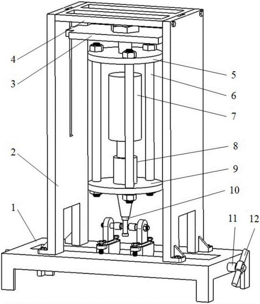
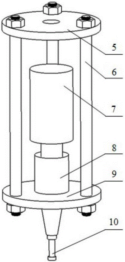
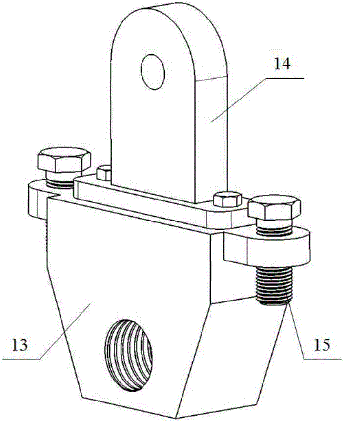
[0046] In this embodiment, when the ultrasonic high-frequency ball wear fatigue test device conducts the high-frequency wear and ultra-high cycle fatigue test of the ball sample, firstly, the ball clamping device and the ultrasonic loading device are installed on the vertical test bench respectively, and then according to the test It is required to install the ball sample 17 on the ball clamping device, and connect the ball clamping device to the ball moving device, then turn the rocking lever 12 to drive the positioning screw 11 to rotate and adjust the axial lateral position of the ball sample, and at the same time pass the slide plate 3 Adjust the longitudinal position of the ultrasonic loading device so that the ball sample 17 is in linear contact with the longitudinal vibration test piece 10 and ensure that the ball sample 17 can roll cyclically. After the position is determined, rotate the compression bolt 15 to lock and position the ball moving device. Finally, start the...

Embodiment 2

[0048] In this embodiment, when the ultrasonic high-frequency ball wear fatigue test device is used to test the ultra-high cycle fatigue performance of the longitudinal vibration test piece under the combined load of high-frequency vibration and rolling wear, a suitable vibration test piece is made according to the test material to be carried out. First, Install the ball clamping device and the ultrasonic loading device on the vertical test bench respectively, then install the ball sample 17 on the ball clamping device according to the test requirements, and connect the ball clamping device to the ball moving device, and then Rotate the rocking rod 12 to drive the positioning screw 11 to rotate and adjust the axial position of the ball sample 17, and at the same time adjust the longitudinal position of the ultrasonic loading device through the slide plate 3, so that the ball sample 17 is in linear contact with the longitudinal vibration test piece 10 and ensures that the ball sa...


PUM


Abstract

The invention discloses an ultrasonic high-frequency ball wear fatigue test device. By the use of an ultrasonic loading mode, the ultra-long cycle fatigue lives of different ball test samples can be tested under the action of a wear load, and the ultra-long cycle fatigue performance of a vibration test piece can be tested under the action of a high-frequency vibrating and rolling wear composite load. A positioning screw drives two ball moving devices to oppositely move in the axial direction; a sliding plate drives an ultrasonic loading device to move along the longitudinal direction of a dovetail groove of a supporting plate, so as to precisely determine a relative position of the ball test sample and the longitudinal vibrating test piece; the longitudinal vibrating test piece bear a longitudinal vibrating high-frequency cyclic load and a rolling wear composite load, so that the ultra-long cycle fatigue performances of different vibrating test piece materials under the action of the composite load can be tested; a longitudinal contact position of the longitudinal vibrating test piece and the ball test sample is adjusted to load vibrating friction displacements with different sizes onto the ball test sample; the ball moving device is connected with a ball clamping device, so that an ultrasonic fatigue test on two ball test samples can be realized at one time.

Description

technical field [0001] The invention relates to the technical field of rolling friction contact fatigue life testing, in particular to an ultrasonic high-frequency ball wear fatigue test device for testing the ultra-high-cycle fatigue life of ball wear and the ultra-high-cycle fatigue performance of vibration specimens under the action of rolling wear . Background technique [0002] In the fields of aerospace and railway transportation industries, mechanical structural components are subjected to the combined action of high-frequency vibration cyclic loads and rolling wear cyclic loads for a long time, and these load cycles are as high as 10 9 ~10 11 Week, which belongs to the category of ultra-high cycle, the composite damage caused by this kind of composite load will greatly accelerate the fatigue failure of mechanical structural parts. Therefore, it has become a new research topic to carry out the ultra-high cycle fatigue life test of high-frequency rolling wear samples...

Claims


Application Information

Patent Timeline
IPC IPC(8): G01N3/56G01N3/32
CPCG01N3/32G01N3/56G01N2203/0055
Inventor 薛红前陈修强李智徐阳
Owner NORTHWESTERN POLYTECHNICAL UNIV
Why Eureka
Try Eureka