

Working area ranking method and ranking system for robot
A technology of working area and sorting method, applied in control/regulation systems, instruments, motor vehicles, etc., can solve the problem of many walking paths of robots, and achieve the effect of improving flexibility, strong stability, and improving cleaning efficiency
- Summary
- Abstract
- Description
- Claims
- Application Information
AI Technical Summary
Problems solved by technology
Method used
Image

Examples
Embodiment Construction
[0044] In order to more clearly illustrate the technical solutions in the embodiments of the present invention or the prior art, the accompanying drawings that need to be used in the description of the embodiments or the prior art will be briefly introduced below. The invention is exemplary and should not be construed as limiting the invention. The following description describes numerous specific details to facilitate an understanding of the present invention. However, in certain instances, well-known or conventional details are not described in order to satisfy the requirement of conciseness of the description.
[0045] The Android device testing method and testing device of the present invention can be written in java language, and can also be implemented in other programming languages such as C#, VB, and C++ / C.
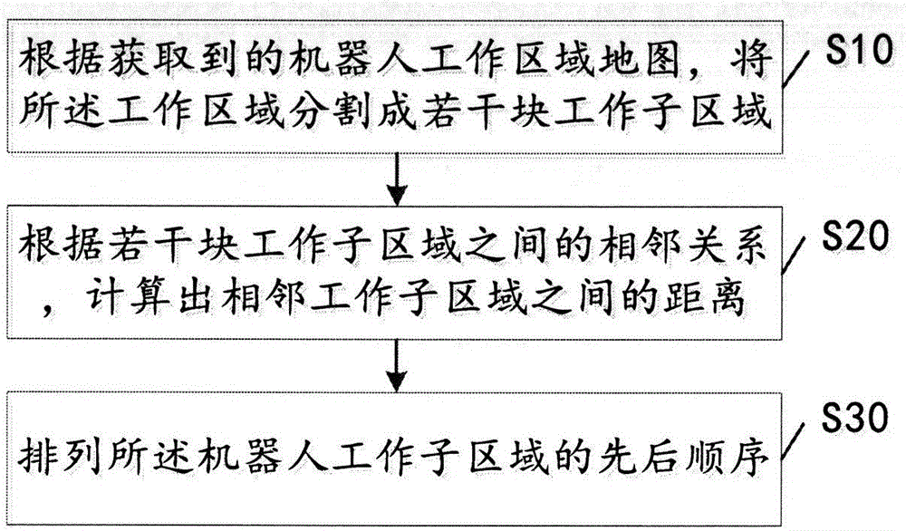
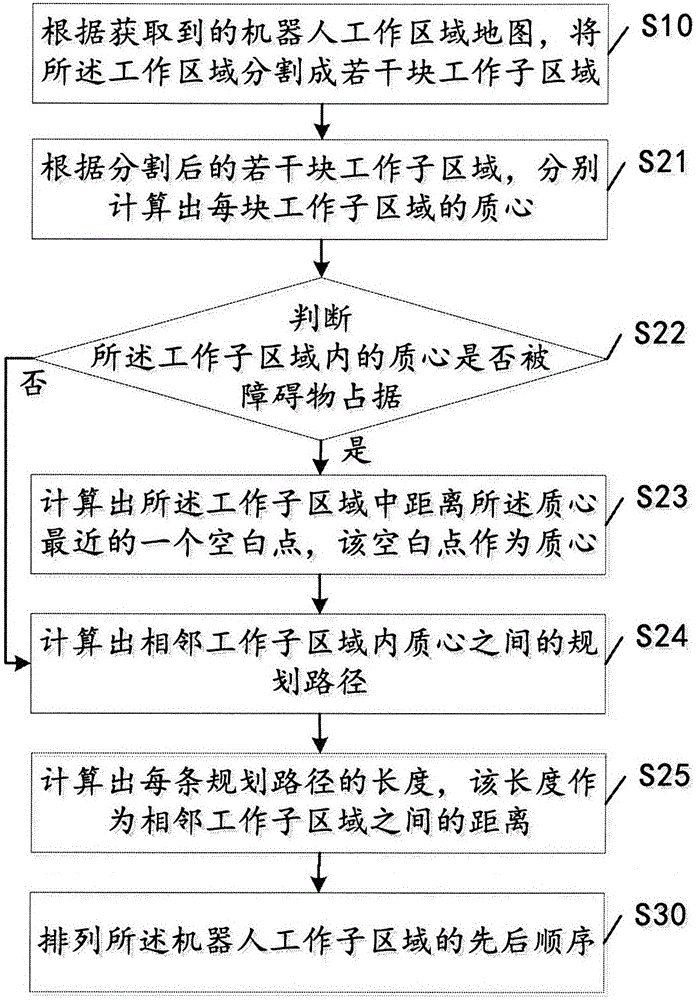
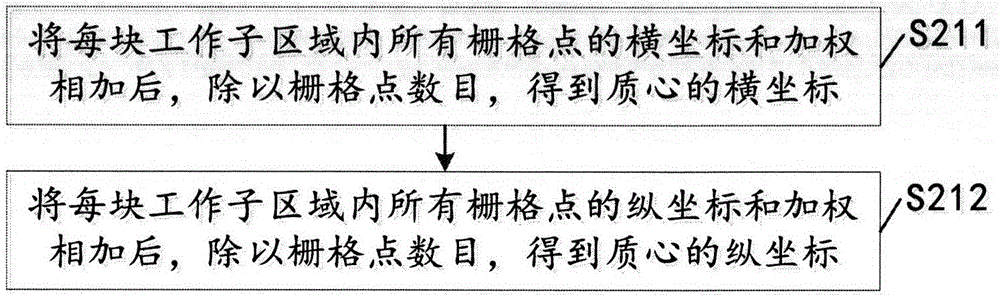
[0046] Such as figure 1 As shown, according to an embodiment of the present invention, a method for sorting the working area of a robot includes the followi...
PUM
 Abstract
Description
Claims
Application Information