Jointless telescopic connector with contact rails

A technology of contact rails and connectors, which is applied in the direction of connection, conductive connection, rail joints, etc., can solve the problems of current collector slipper and related connection mechanism damage, unfavorable current collection, instability, etc., so as to improve the working life and The effect of vehicle running speed, elimination of abnormal impact noise and unstable flow

Active Publication Date: 2016-07-06
HUNAN HUAPIN RAIL TRANSIT CO LTD
View PDF6 Cites 15 Cited by
  • Summary
  • Abstract
  • Description
  • Claims
  • Application Information

AI Technical Summary

Problems solved by technology

Through actual use, it is found that when the current collector passes through the expansion joint with expansion joints, the collector shoe is affected by the expansion joint, the larger the joint, the greater the impact, and the faster the speed, the more obvious the impact, from the normal plane contact state The attitude changes, and after completely passing the expansion joint, it returns to the no

Method used


Image

  • Jointless telescopic connector with contact rails
  • Jointless telescopic connector with contact rails
  • Jointless telescopic connector with contact rails

Examples


Embodiment 1

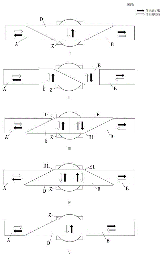
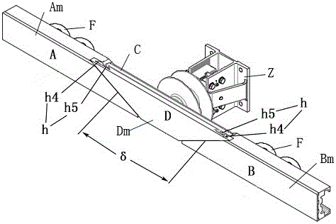
[0026] Embodiment one: according to figure 1 (I) and figure 2 As shown, a C-shaped contact rail adopts a telescopic connector with a slide rail chute transmission mechanism without expansion joints, and the limit guide (C) is respectively inserted into the C-shaped grooves of two C-shaped contact rail segments (A, B). , there is a sliding gap between the contact rail segment and the limit guide body, the two contact rail segments (A, B) can only slide along the length of the contact rail; a contact surface slider (D), the slider partially or completely Cover the telescopic gap (δ), and the outer contact surfaces (Am, Bm) of the two contact rail segments (A, B) and the outer contact surface (Dm) of the contact surface slider (D) are always in the same plane in three-dimensional space , so that the current collector passes through without impact; the transmission mechanism (h) is composed of the guide rail (h4) set on the contact surface slider (D) and the guide dovetail groov...

Embodiment 2

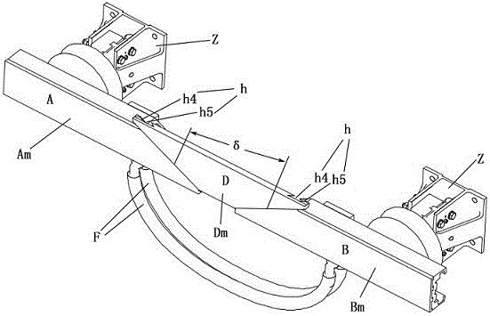
[0027] Embodiment two: according to figure 1 (I), image 3 As shown, a C-shaped contact rail adopts a telescopic connector with no expansion joints in the slide rail chute transmission mechanism, and has a limit guide (C) (insulator upper accessory chuck) respectively snapped into the C-shaped grooves of the two C-shaped contact rail sections (A, B), and the two contact rail sections (A, B) can freely expand and slide in the direction of their length; There is a contact surface slider (D) which completely or partially covers the telescopic gap (δ) and the outer contact surfaces (Am, Bm) of the two contact rail segments (A, B) and The outer contact surface (Dm) of the contact surface slider (D) is always in the same plane in three-dimensional space, so that the current receiver can pass through without impact; the transmission mechanism (h) is controlled by the guide rail (h4) set on the contact surface slider (D) ) and the guide dovetail groove (h5) set on the guide limit bo...

Embodiment 3

[0028] Embodiment three: according to figure 1 (Ⅲ), Figure 4As shown, a C-shaped contact rail adopts a telescopic connector with no expansion joints in the rack and pinion transmission mechanism. The two ends of the limit guide (C) are inserted into the two contact rail segments (A, B) and maintain an appropriate sliding gap. , the two contact rail sections (A, B) can freely stretch and slide in their long direction; two contact surface sliders (D, E) are installed on the limit guide body (C), and two contact surface sliders ( D, E) Cover the telescopic gap (δ), and always maintain an adjoining relationship with the two contact rail segments (A, B), and the outer contact surfaces (Am, Bm) of the two contact rail segments (A, B) and the contact The outer contact surfaces (Dm, Em) of the surface sliders (D, E) are always in the same plane in three-dimensional space, so that the current collector can pass through without impact; the contact surface slider (D) and the limit guid...


PUM


Abstract

The invention relates to a jointless telescopic connector with contact rails. The jointless telescopic connector with the contact rails comprises two contact rail segments, a limiting guide body, a contact surface slide block and an electrical conductor, wherein the two contact rail segments are in connecting fit with sliding clearances through the limiting guide body; at least one contact surface slide block is arranged on the limiting guide body or substrates of the contact rail segments; the external contact surface of the contact surface slide block and the external contact surfaces of the contact rail segments are located on the same working surface; the contact surface slide block partially or completely covers a telescopic gap between the two contact rail segments; at least one edge of the contact surface slide block is a bevel edge; the included angle of the sideline of the bevel edge and the telescopic direction of the contact rail segments is smaller than 90 degrees; when the two contact rail segments displace in the length direction to cause a change of the telescopic gap, the contact surface slide block correspondingly displaces along the direction vertical to the telescopic direction of the contact rail segments to adapt to the change of the telescopic gap on the contact working surface; and meanwhile, at least one electrical conductor is connected with the limiting guide body or/and the two contact rail segments to achieve electrical conduction.

Description

technical field [0001] The invention relates to a telescopic connector for rail transit contact rail system. Background technique [0002] The main function of this type of telescopic connector is to compensate the length change of the contact rail due to temperature and mechanical displacement and the electrical connection of the contact rail. For the telescopic connector described in the invention patent specification of China Authorized Notice No. CN102427172B, the currently used telescopic connector has better solved the thermal expansion and contraction of the contact rail system, mechanical displacement, current transmission, elimination of adjacency force and expansion and contraction. However, the solution and product still have design flaws, the main flaws are described as follows: [0003] In the prior art, measures taken by this type of telescopic connector to deal with length changes caused by thermal expansion and contraction of the contact rail and mechanical ...

Claims


Application Information

Patent Timeline
IPC IPC(8): H01R11/00H01R41/00
CPCB60M1/305E01B11/00H01R25/145H01R11/00H01R41/00
Inventor 曾鉴姜兴振李贵航邓茂涛
Owner HUNAN HUAPIN RAIL TRANSIT CO LTD
Why Eureka
Try Eureka