Converter system and control method thereof

A technology of a converter system and a control method, which is applied in the field of converters and can solve problems such as wind turbine downtime due to failure

Active Publication Date: 2016-07-06
CSR ZHUZHOU ELECTRIC LOCOMOTIVE RES INST
View PDF6 Cites 9 Cited by
  • Summary
  • Abstract
  • Description
  • Claims
  • Application Information

AI Technical Summary

Problems solved by technology

[0008] In view of this, the purpose of the present invention is to provide a converter system and its control method, which can solve the technical problem of wind turbine

Method used


Image

  • Converter system and control method thereof
  • Converter system and control method thereof
  • Converter system and control method thereof

Examples


Embodiment 1

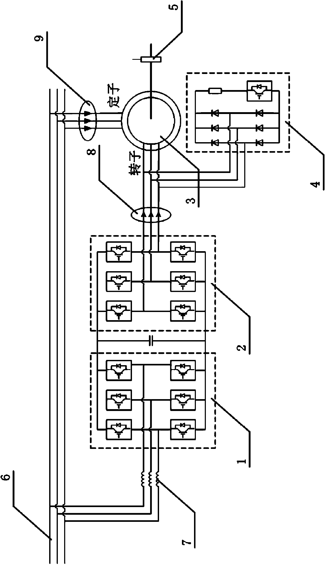
[0084] as attached figure 1 And attached Figure 4 As shown, a specific embodiment of a converter system includes: a converter, a motor 3, a speed sensor 5 and a control device 10. When the converter system is in normal operation, the control device 10 uses the rotor speed sampled by the speed sensor 5 The position signal controls the converter, and monitors the state of the speed sensor 5 in real time according to the rotor current error of the motor 3 . As a typical specific embodiment of the present invention, the motor 3 further adopts a doubly-fed motor. When the signal of the speed sensor 5 is abnormal, the control device 10 uses the estimated rotor position signal instead of the rotor position signal sampled by the speed sensor 5 to control the converter. The converter further includes a grid-side converter 1, a generator-side converter 2, and a crowbar circuit 4. The AC terminal of the grid-side converter 1 is connected to the grid 6 through a grid-side inductor 7, a...

Embodiment 2

[0088] A specific embodiment of a converter system control method, comprising the following steps:

[0089] S11: when the converter is running normally, the control device 10 uses the rotor position signal sampled by the speed sensor 5 to control the converter, and monitors the state of the speed sensor 5 in real time according to the rotor current error of the motor 3;

[0090] S12: When the signal of the speed sensor 5 is abnormal, the control device 10 uses the estimated rotor position signal instead of the rotor position signal sampled by the speed sensor 5 to control the converter.

[0091] as attached Figure 11 As shown, a more specific embodiment of the above-mentioned converter system control method includes the following steps:

[0092] S101: When the converter is running normally, the machine-side converter 2 is controlled using the rotor position signal and the rotor speed signal sampled by the speed sensor 5;

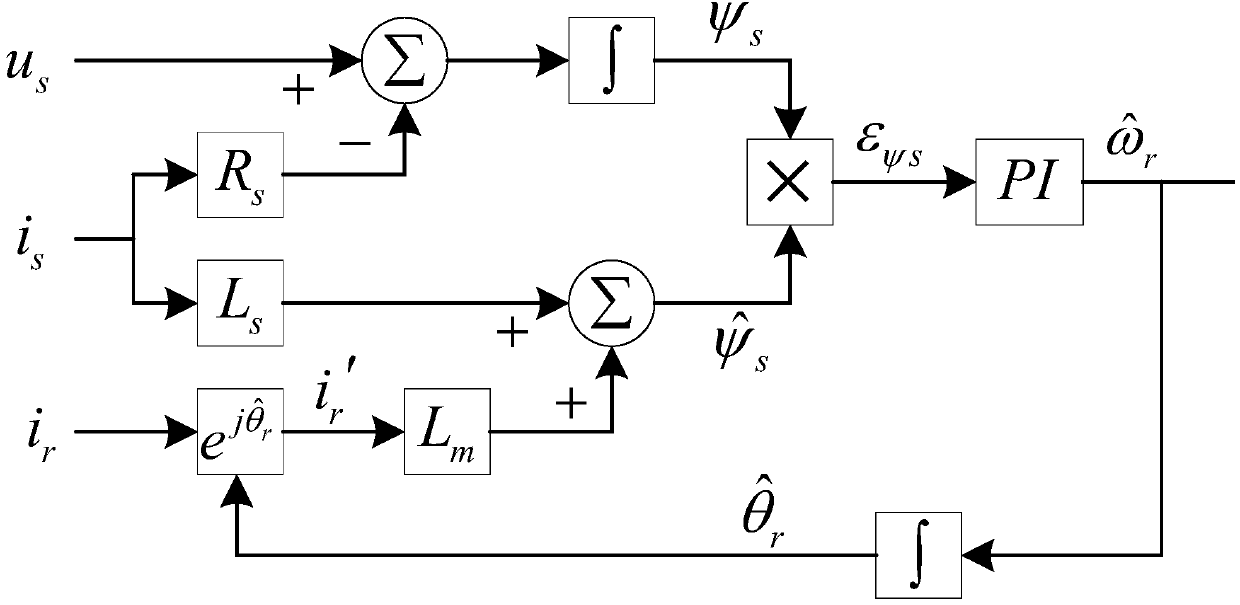
[0093] S102: the rotor position estimation unit of ...


PUM


Abstract

The invention discloses a converter system and a control method thereof. The converter system comprises a converter, a motor, a speed sensor and a control device. When the converter system works normally, the control device controls the converter by employing a rotor position signal sampled by the speed sensor; and the state of the speed sensor is monitored in real time according a rotor current error of the motor. When the signal of the speed sensor is abnormal, the control device employs a rotor position estimation signal to replace the rotor position signal sampled by the speed sensor to control the converter. According to the invention, with the system and the control method, a technical problem that the converter system shuts down due to fault occurrence after abnormity of the speed sensor signal can be solved; the shutdown time of the converter system before maintenance can be reduced; and the system stability can be improved under the circumstance that the speed sensor signal is abnormal.

Description

technical field [0001] The invention relates to the field of converter technology, in particular to a system for improving the operating performance of a wind power converter when a speed sensor signal is abnormal and a control method thereof. Background technique [0002] Wind power is currently the fastest growing renewable energy utilization method with the most prospects for large-scale and commercial development. Double-fed power generation technology is more suitable for megawatt-level high-power variable-speed constant-frequency wind power generation, and occupies a very important position in wind power generation systems. For doubly-fed motor control, its control performance has a great dependence on the accurate detection of speed and rotor position. In the doubly-fed wind power system, the speed sensor is a type of component with a high failure rate. The electromagnetic conditions of the working environment of the speed sensor are relatively harsh, and the signal...

Claims


Application Information

Patent Timeline
IPC IPC(8): H02J3/38H02P21/14H02P101/15
Inventor 张少云
Owner CSR ZHUZHOU ELECTRIC LOCOMOTIVE RES INST
Why Eureka
Try Eureka