Sliding door module/pivoting sliding door module having floating mounting of a rack of a rack-and-pinion drive

A sliding door and rack technology, which is applied to door devices, door/window accessories, and suspension devices of wing leaves, etc., can solve the problems of poor energy efficiency of rail vehicles, unfavorable total weight and heavy weight of rail vehicles, etc.

Inactive Publication Date: 2016-07-06
KNORR BREMSE GMBH
View PDF10 Cites 9 Cited by
  • Summary
  • Abstract
  • Description
  • Claims
  • Application Information

AI Technical Summary

Problems solved by technology

The structures used according to the prior art are therefore designed relatively rigidly and correspondingly heavy, which is also detrimental to the overall weight of the rail vehicle
Especially in urban traffic in which the rail vehicle accelerates and then brakes over short distances, such a support structure impairs the energy efficiency of the rail vehicle

Method used


Image

  • Sliding door module/pivoting sliding door module having floating mounting of a rack of a rack-and-pinion drive
  • Sliding door module/pivoting sliding door module having floating mounting of a rack of a rack-and-pinion drive
  • Sliding door module/pivoting sliding door module having floating mounting of a rack of a rack-and-pinion drive

Examples


Embodiment Construction

[0031] At the outset, it should be pointed out that, in the different described embodiments, the same components are provided with the same symbols or the same component designations, and that the disclosure contained in the entire description is sensibly applicable to the same components with the same symbols or the same component designations. Positional descriptions mentioned in the description, eg top, bottom, side, etc., refer to the directly illustrated and described drawing and, in the event of a change in position, apply to the new position as such. Furthermore, individual features or combinations of features from the various exemplary embodiments shown and described form their own independent solutions, innovative solutions or solutions according to the invention.

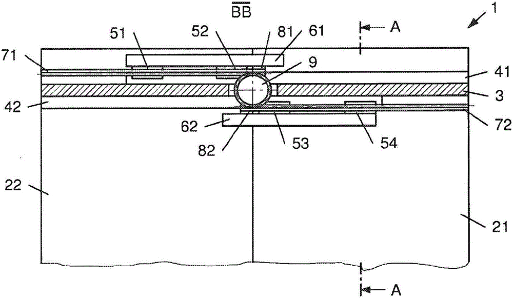
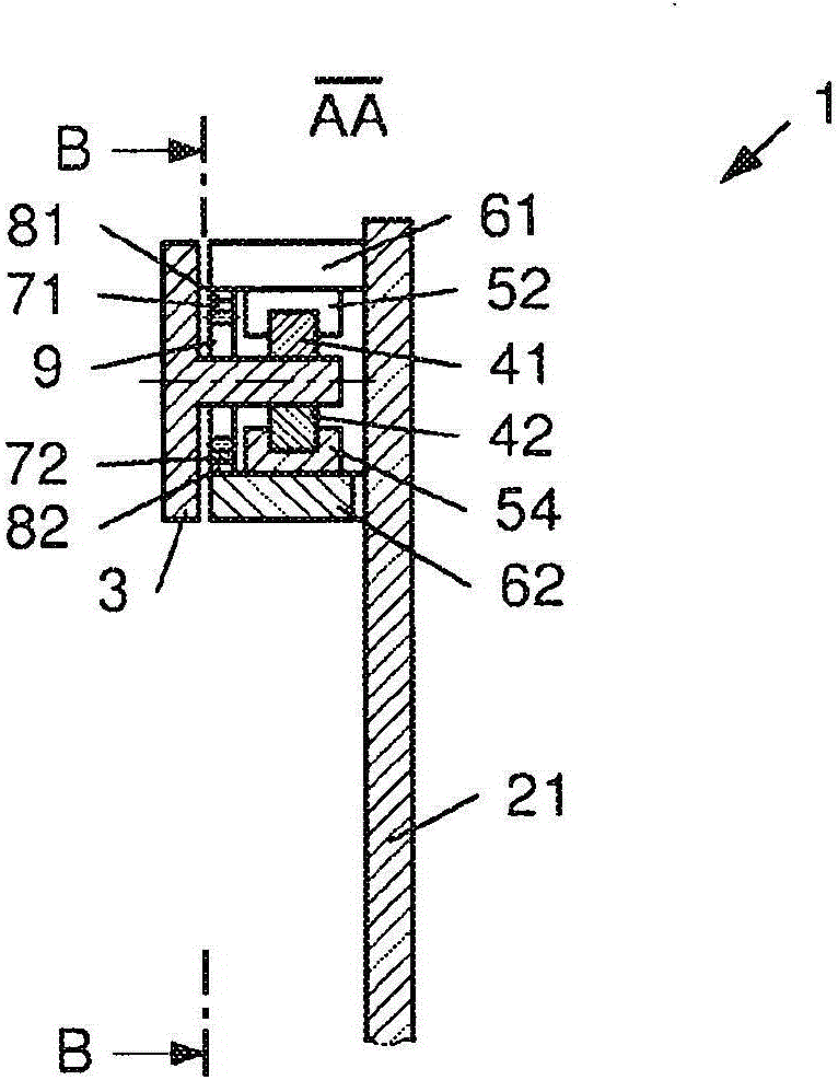
[0032]figure 1 and 2 A schematically depicted and exemplary sliding door module / swing sliding door module 1 for a rail vehicle is shown, which comprises two door leaves 21 , 22 and a sliding direction of t...


PUM


Abstract

The invention relates to a sliding door module/pivoting sliding door module (1) for a rail vehicle, which comprises a door leaf (21, 22) and a support (3), which is aligned longitudinally in the sliding direction of the door leaf (21, 22) and is mounted such that the support (3) can be displaced in the horizontal direction in particular transversely to the longitudinal extent thereof. The sliding door module/pivoting sliding door module (1) also has a linear guide for mounting the door leaf (21, 22), which is fastened to or integrated in the support (3). The door leaves (21, 22) are moved with the aid of a rack-and-pinion drive. The rack-and-pinion drive has a rack (71, 72), which is coupled only in the first end region thereof to the door leaf (21, 22), and the floating end of which is engaged with a gearwheel (9) that is mounted rotatably in the support (3).

Description

technical field [0001] The invention relates to a sliding door module / swing sliding door module for a rail vehicle, said sliding door module / swinging sliding door module comprising a door leaf, a support and a linear guide, the support being along the sliding direction of the door leaf Oriented longitudinally, the support is mounted slidably in the horizontal direction, in particular transversely to its longitudinal extension, the linear guide comprises a profiled rail and at least one guide slide mounted slidably on the profiled rail seat or guide carriage. The profiled rail is fastened to the support or is included in the support in the form of a support-shaped region. The door leaf is slidably mounted by means of the at least one guide carriage / guide carriage. Background technique [0002] Sliding door modules / swing sliding door modules of the type described above are known in principle. In this case, in most cases one door leaf or two door leaves are slidably mounted,...

Claims


Application Information

Patent Timeline
Patent Type & Authority Applications(China)
IPC IPC(8): B61D19/00
CPCB61D19/00B61D19/005E05D15/0604E05D15/0652E05F15/00E05Y2900/51E06B3/4636E06B3/50
Inventor A·梅尔H·扎尔A·顺克
Owner KNORR BREMSE GMBH
Why Eureka
Try Eureka