Method of manufacturing engine crankshaft and laser shock reinforcing device of engine crankshaft

A manufacturing method and laser shock technology, applied in the direction of manufacturing tools, furnace types, furnaces, etc., can solve the problems of difficult to guarantee laser strengthening, labor and time-consuming, high fixture manufacturing cost, and achieve increased hardness, increased service life, and improved impact toughness. Effect

Active Publication Date: 2016-07-13
JIANGSU UNIV
View PDF4 Cites 7 Cited by
  • Summary
  • Abstract
  • Description
  • Claims
  • Application Information

AI Technical Summary

Problems solved by technology

Not only labor-intensive and time-consuming, but also difficult to guarantee the effect of laser strengthening
Due to the variety of crankshafts and different eccentric distances, each set of fixtures needs an eccentric packing, resulting in high fixture manufacturing costs

Method used


Image

  • Method of manufacturing engine crankshaft and laser shock reinforcing device of engine crankshaft
  • Method of manufacturing engine crankshaft and laser shock reinforcing device of engine crankshaft

Examples


Embodiment Construction

[0021] The technical solution of the present invention will be described in more detail below in conjunction with the accompanying drawings.

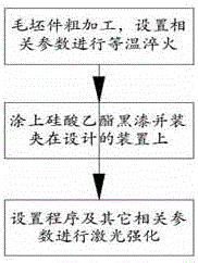
[0022] Such as figure 1 As shown, the engine crankshaft processing process is: ductile iron blank → rough machining → austempering treatment → laser shock surface strengthening → finishing → finished crankshaft. Specifically: Step 1: Roughly process the nodular cast iron blank of the crankshaft to form the crankshaft primary product; Step 2: Perform austempering on the crankshaft primary product; Step 3: Perform laser shock surface strengthening on the crankshaft primary product after austempering Processing; Step 4: Finishing the primary crankshaft after the laser shock surface strengthening treatment, and finally forming the finished crankshaft.

[0023] Preferably, after the rough machining of the crankshaft, put it into an overturning trolley-type quenching furnace and heat it to 850±20°C, keep it warm for 90 minutes, and then leav...


PUM

PropertyMeasurementUnit
thicknessaaaaaaaaaa
diameteraaaaaaaaaa

Abstract

The invention relates to a method of manufacturing an engine crankshaft and a laser shock reinforcing device of the engine crankshaft.The method comprises the steps: (1), heating in a rotary trolley type quenching furnace, to 850 +/- 20 DEG C, and holding the temperature for 90 min; (2), soaking in a nitrate bath for isothermal maintaining at isothermal temperature of 350 DEG C for 60 min.After isothermal quenching, crankshaft surface is reinforced by laser shock reinforcement.A laser shock reinforcing apparatus comprises a high-power pulse laser, a laser splitter, a movable laser reflector, a movable laser focusing lens, a crankshaft rotation drive device, a water nozzle, a guide rail sliding mechanism and a CNC (computer numerical control) device; by superposing two processes, matrix strength, surface hardness and wear resistance of a crankshaft are improved effectively; in addition, the reinforcing apparatus of the invention uses two laser beams to reinforce fillets of the crankshaft, and the production efficiency is high.

Description

technical field [0001] The invention belongs to the technical field of metal material heat treatment and laser shock strengthening, and in particular relates to a manufacturing method of an engine crankshaft and a laser shock strengthening theory thereof. Background technique [0002] At present, the existing engine industry generally adopts fillet rolling and shot peening to strengthen the crankshaft to improve the fatigue strength and safe service life of the crankshaft. However, due to the limitation of the crankshaft processing technology in fillet rolling, it is difficult for the fillets of the journals to coincide with the rollers, which often results in the phenomenon of gnawing and cutting of the fillets, and the deformation of the crankshaft after rolling is large, and the effect is not good. Shot peening can effectively avoid the above situation, but the shot peening process has a great influence on the surface roughness of the crankshaft, and the residual compress...

Claims


Application Information

Patent Timeline
Patent Type & Authority Applications(China)
IPC IPC(8): C21D1/20C21D1/09C21D9/30
CPCC21D1/09C21D1/20C21D9/30
Inventor 任旭东胡征征李琳任云鹏佟艳群孙建荣周睿叶召
Owner JIANGSU UNIV
Why Eureka
Try Eureka