Folded-plate truss concrete assembly

A concrete and slab truss technology, which is applied in building components, building structures, buildings, etc., can solve the needs of construction projects that cannot achieve large spans, the increase in the amount of steel bars for cast-in-place components, and the inconvenience of pre-embedding and installation of wire boxes. Convenience and other issues, to achieve the effect of easy pre-embedding and installation of the wire box, high overall bearing capacity, and reduced cost

Pending Publication Date: 2016-07-13
SHANDONG ONE STAR CO NSTRUCTION TECH CO LTD
View PDF4 Cites 0 Cited by
  • Summary
  • Abstract
  • Description
  • Claims
  • Application Information

AI Technical Summary

Problems solved by technology

[0002] At present, the base plates of laminated boxes and laminated slabs used in various construction projects are all made of reinforced concrete slabs. In long-term use, it is found that this reinforced concrete slab has many shortcomings: the thickness of the plate is relatively large, and the weight is relatively large. Increase the bearing capacity in engineering application structures; due to the small cross-sectional area and low flexural bearing capacity, it is impossible to meet the needs of large-span construction projects; when a project with a large section moment of inertia is required, a large number of steel bars need to be configured to ensure that The safety in the hoisting and construction process makes the construction complicated and the construction progress is slow; it is not easy to combine with other components; due to the large thickness of the bottom plate, it is difficult to determine the force of the two-way plate structure in the components, resulting in the use of cast-in-place The amount of reinforcement used in the components has increased significantly, and the pre-embedding and installation of the wire box is inconvenient, etc.

Method used


Image

  • Folded-plate truss concrete assembly
  • Folded-plate truss concrete assembly
  • Folded-plate truss concrete assembly

Examples


Embodiment Construction

[0007] The present invention will be further described with reference to the accompanying drawings.

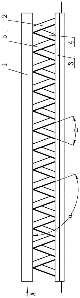
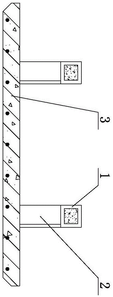
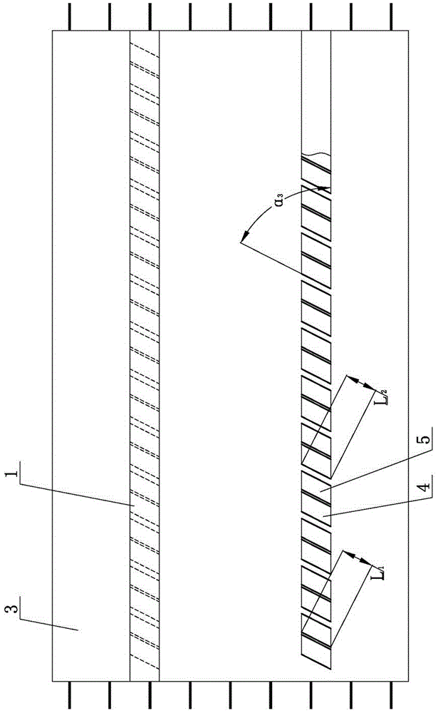
[0008] The concrete member of the folded plate truss of the present invention comprises a base plate 3, protruding steel bars are arranged on both sides of the base plate 3, and a folded plate type truss is arranged on the surface of the base plate 3, and the folded plate type truss is composed of a connecting rod 1 and several folded plates, the folded plates One end is connected to the surface of the bottom plate 3, and the other end of the folded plate is connected to the connecting rod 1. The folded plate is composed of several first inclined plates 2 and several second inclined plates 4, and the several first inclined plates 2 are distributed parallel to each other. The second slant plates 4 are distributed parallel to each other, and a second angle α is set between each first slant plate 2 and each second slant plate 4 2 .

[0009] According to the present invention, th...


PUM


Abstract

A folded-plate truss concrete assembly comprises a bottom plate.Protruding rebars are arranged on the two sides of the bottom plate, a folded-plate truss is arranged on the surface of the bottom plate and composed of a connecting rod and multiple folded plates, one end of each folded plate is connected with the surface of the bottom plate, and the other end of each folded plate is connected with the connecting rod; each folded plate is composed of multiple first inclined plates and multiple second inclined plates, the first inclined plates are distributed in parallel, the second inclined plates are distributed in parallel, and a second included angle alpha<2> is formed between each first inclined plate and the corresponding second inclined plate.According to the folded-plate truss concrete assembly, the defects in the prior art can be overcome, the thickness of the bottom plate can be greatly reduced, loads of other components in engineering are reduced, and the construction cost of a main structure is reduced; the inertia moment of the section is large, stress is uniform and reasonable, and in the engineering construction process, the safety of hoisting and construction processes is high, rebars do not need to be arranged, and meanwhile the engineering construction cost is reduced.

Description

technical field [0001] The invention relates to construction engineering, which is a folded plate truss concrete component. Background technique [0002] At present, the base plates of laminated boxes and laminated slabs used in various construction projects are all made of reinforced concrete slabs. In long-term use, it is found that this reinforced concrete slab has many shortcomings: the thickness of the plate is relatively large, and the weight is relatively large. Increase the bearing capacity in engineering application structures; due to the small cross-sectional area and low flexural bearing capacity, it is impossible to meet the needs of large-span construction projects; when a project with a large section moment of inertia is required, a large number of steel bars need to be configured to ensure that The safety in the hoisting and construction process makes the construction complicated and the construction progress is slow; it is not easy to combine with other compo...

Claims


Application Information

Patent Timeline
Patent Type & Authority Applications(China)
IPC IPC(8): E04C2/32E04C2/52
CPCE04C2/322E04C2/50E04C2/52
Inventor 张波张树辉
Owner SHANDONG ONE STAR CO NSTRUCTION TECH CO LTD
Why Eureka
Try Eureka