A carbon fiber anchor

A carbon fiber board and anchoring technology, which is used in buildings, building reinforcements, building components, etc., can solve the problems of low anchoring efficiency, damaged carbon fiber boards, and inability to adjust, and achieves high anchoring efficiency. The effect of distance reduction

Active Publication Date: 2018-10-26
浙江固周科技有限公司
View PDF7 Cites 0 Cited by
  • Summary
  • Abstract
  • Description
  • Claims
  • Application Information

AI Technical Summary

Problems solved by technology

[0003] At present, when most anchorages are used to anchor the carbon fiber plate, the carbon fiber plate is clamped in the groove by two splints with grooves on the inner surface, and the carbon fiber plate is set up and down through the two sides of the clip. The bolt locking mechanism makes the two clips firmly clamp the carbon fiber plate. The carbon fiber plate at the anchorage area of ​​the anchorage with this structure not only needs a splint with a certain thickness to ensure the anchoring strength, so the overall volume is large. It takes up a lot of space, and the compressive stress from the loaded end to the free end is basically consistent, and the compressive stress on each part of the carbon fiber plate cannot be adjusted separately, so the carbon fiber plate always bears a large compressive stress at the loaded end , it is easy to cause damage to the carbon fiber plate in this area, so that the carbon fiber plate will be damaged in advance before its ultimate tensile strength is fully realized, so the anchoring efficiency of the anchorage used to anchor the carbon fiber plate is not high

Method used


Image

  • A carbon fiber anchor
  • A carbon fiber anchor
  • A carbon fiber anchor

Examples


Embodiment 1

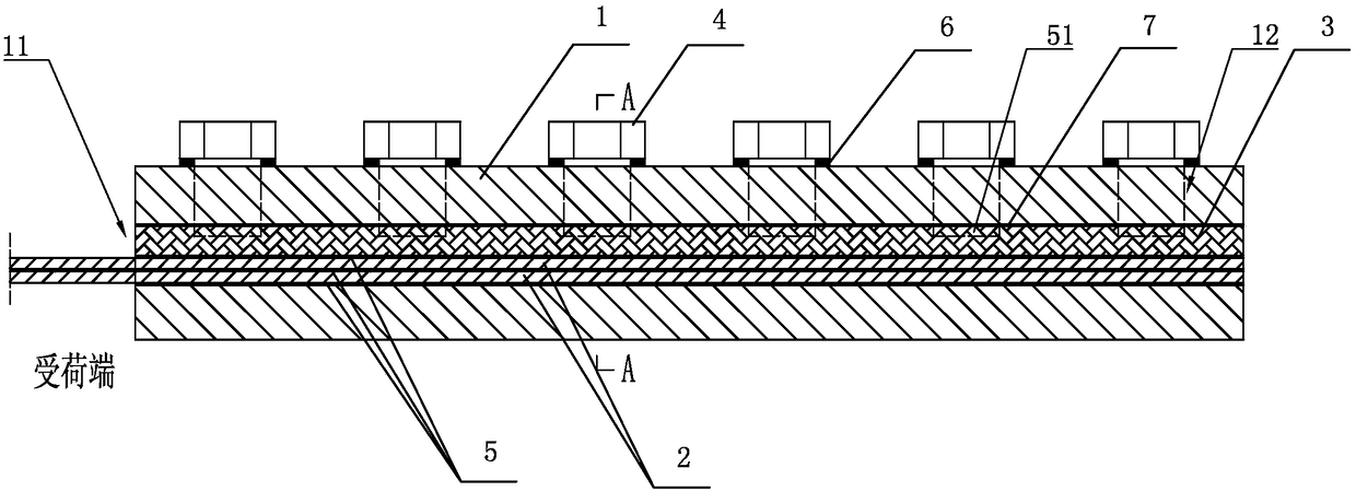
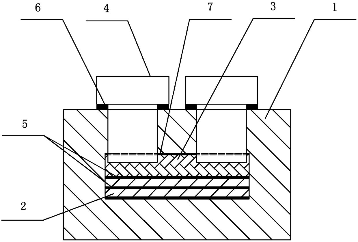
[0018] Embodiment 1: A carbon fiber plate anchor, including an anchor barrel 1 and two carbon fiber plates 2, an anchoring groove 11 is arranged in the anchor barrel 1, and a carbon fiber plate 2 is set in the anchoring groove 11. The carbon fiber plate 2 and the anchor barrel 1 A force transmission backing plate 3 is arranged between the force transmission backing plate 3 and the carbon fiber plate 2, between adjacent carbon fiber plates 2, and between the carbon fiber plate 2 and the anchor tube 1. Colloid 5, the upper part of the anchor cylinder 1 is provided with multiple rows of compression screw hole groups in the axial direction, each row of compression screw hole groups includes a compression screw hole 12, and compression bolts 4 are arranged in the compression screw hole 12, A first sealing device 6 is arranged between the compression bolt 4 and the anchor cylinder 1 , and the compression bolt 4 is tightly pressed on the force transmission backing plate 3 .

Embodiment 2

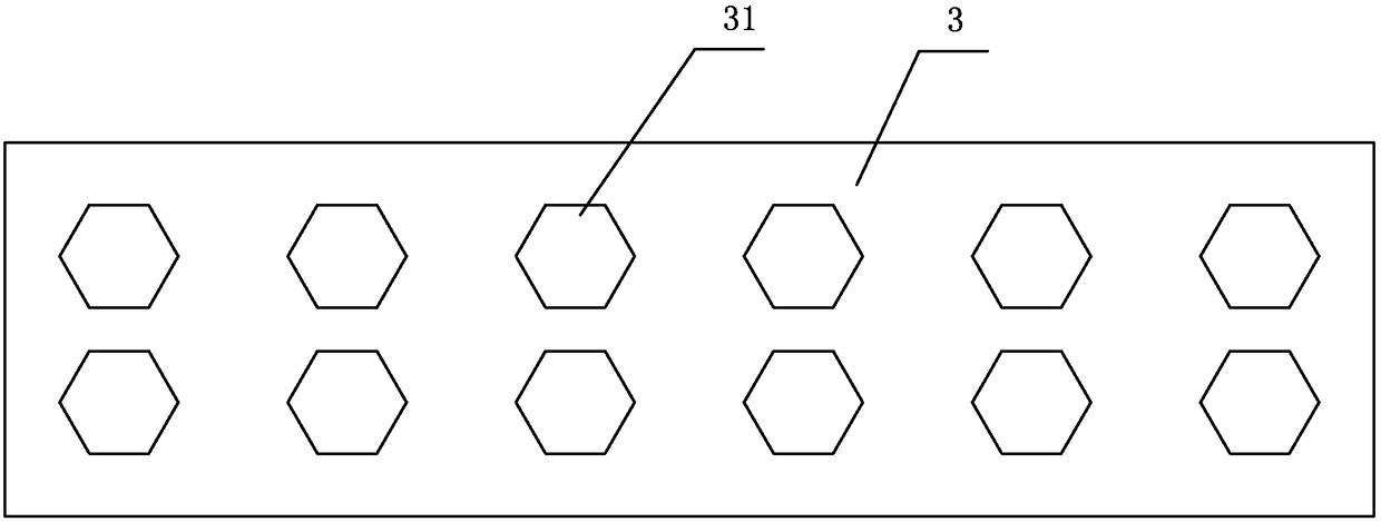
[0019] Embodiment 2: The remaining parts are the same as in Embodiment 1, the difference is that the force transmission backing plate 3 is provided with a compression counterbore 31 corresponding to the compression screw hole 12 one by one, and the compression bolt 4 is embedded in the compression screw hole 12. In the counterbore 31, the anchor barrel 1 and the force transmission backing plate 3 are all made of steel.

Embodiment 3

[0020] Embodiment 3: The rest is the same as Embodiment 1, the difference is that each row of compression screw hole groups includes two compression screw holes 12 .


PUM


Abstract

The invention discloses an anchorage device for carbon fiber plates. The anchorage device comprises an anchorage cylinder and at least two carbon fiber plates and is characterized in that an anchorage groove is formed in the anchorage cylinder, the carbon fiber plates are arranged in the anchorage groove, a force transferring base plate is arranged between each carbon fiber plate and the anchorage cylinder, protective colloids are arranged between the adjacent carbon fiber plates and between each carbon fiber plate and the anchorage cylinder, multiple rows of pressing screw hole groups are sequentially and axially formed in the upper part of the anchorage cylinder, each row of pressing screw hole groups comprises at least one pressing screw hole, a pressing bolt is arranged in each pressing screw hole, a first sealing device is arranged between each pressing bolt and the anchorage cylinder, and the pressing bolts are pressed on the force transferring base plates. The anchorage device has the advantages as follows: the pressing effect is better, the pressure stress borne by each carbon fiber plate at the corresponding load-bearing end is smaller through adjustment of the pressing bolts, accordingly, the tensile strength property of the carbon fiber plates is sufficiently developed, and the anchorage efficiency is higher.

Description

technical field [0001] The invention relates to an anchorage structure, in particular to a carbon fiber plate anchorage. Background technique [0002] Carbon Fiber Reinforced Polymer / Plastic (CFRP) has outstanding advantages such as light weight, high strength, high modulus, and corrosion resistance. It has been widely used in aerospace, automobile, civil engineering and other fields. Components composed of carbon fiber plates mainly composed of carbon fiber reinforced composite materials have been widely used in the reinforcement and maintenance of civil engineering structures such as bridge engineering and housing construction. [0003] At present, when most anchorages are used to anchor the carbon fiber plate, the carbon fiber plate is clamped in the groove by two splints with grooves on the inner surface, and the carbon fiber plate is set up and down through the two sides of the clip. The bolt locking mechanism makes the two clips firmly clamp the carbon fiber plate. Th...

Claims


Application Information

Patent Timeline
Patent Type & Authority Patents(China)
IPC IPC(8): E04C5/12
CPCE04C5/12
Inventor 诸葛萍郭书峰
Owner 浙江固周科技有限公司
Why Eureka
Try Eureka