Retarder, agitator and agitating lorry

A technology of reducer and power input end, which is applied in the field of agitating transport tank trucks. It can solve the problem that the reducer cannot adapt to the normal transmission of the axis of rotation and the axis of rotation of the reducer. It achieves the effect of reducing maintenance costs and facilitating operation and maintenance.

Inactive Publication Date: 2016-07-13
朱清泉
View PDF6 Cites 0 Cited by
  • Summary
  • Abstract
  • Description
  • Claims
  • Application Information

AI Technical Summary

Problems solved by technology

[0007] The purpose of the present invention is to provide a reducer to solve the problem that the existing reducer cannot adapt to the rotation axis of the carrier such as the mixing tank and the rotation axis of the reducer and continue normal transmission.

Method used


Image

  • Retarder, agitator and agitating lorry
  • Retarder, agitator and agitating lorry
  • Retarder, agitator and agitating lorry

Examples


Embodiment 1

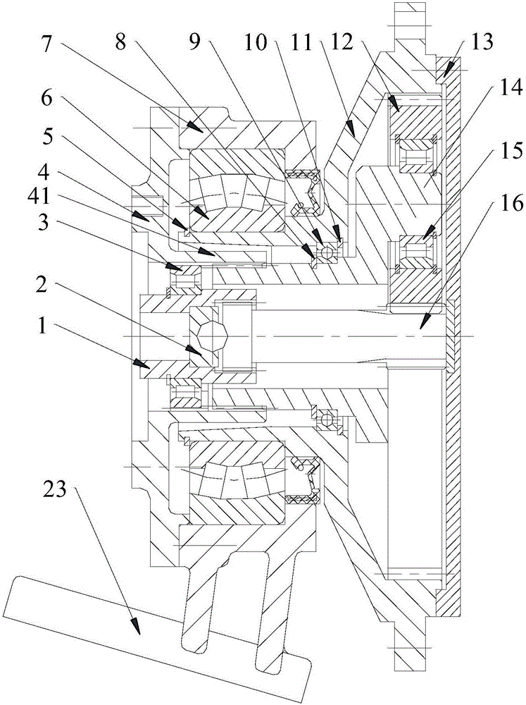
[0071] Please refer to figure 2 According to the first embodiment of the present invention, a speed reducer mainly includes: a box body 7 , an input sleeve 1 , a sun gear 16 , a planetary carrier 14 , a planetary gear 12 , a conjoined ring gear 11 and an end cover 13 .

[0072] Among them, the box body 7 is equipped with a detachable fixed cover 4 at its power input end; the input sleeve 1 is installed in the fixed cover 4 through the first bearing 3; the sun gear 16 is coaxially arranged with the input sleeve 1, and the input sleeve 1 and the sun gear The gears between 16 are connected and transmit power, and a universal swing joint mechanism is arranged between the input sleeve 1 and the sun gear 16.

[0073] The planetary carrier 14 is sleeved on the outside of the sun gear 16 and coaxially arranged with the sun gear 16; the planetary carrier 14 is connected with the fixed cover 4 in rotation, and the planetary carrier 14 is installed with the planetary gear 12 through the...

Embodiment 2

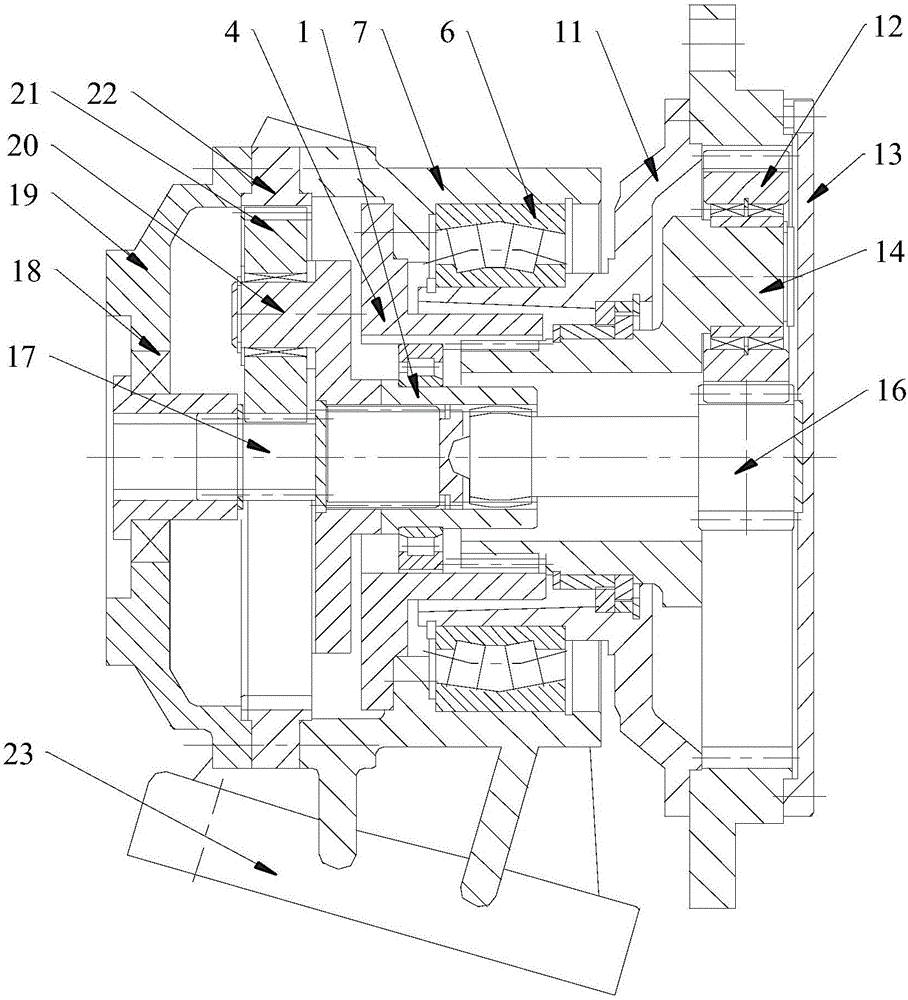
[0093] Such as image 3 As shown, the reducer in the second embodiment mainly includes: a box body 7, an input sleeve 1, a sun gear 16, a planetary carrier 14, a planetary gear 12, a conjoined ring gear 11, an end cover 13, an outer cover 19, a first-stage Sun gear 17, primary planet carrier 20 and primary planetary gear 21. Wherein, in the figure, the sun gear 16 is a secondary sun gear corresponding to the primary sun gear 17, the planet carrier 14 is a secondary planet carrier corresponding to the primary planet carrier 14, and the planetary gear is a secondary planet carrier corresponding to the primary planetary gear 21. Secondary planetary gear.

[0094] Such as image 3 As shown, the outer cover 19 positioned at the outer side of the fixed cover 4 is fixed on the box body 7; the first-level sun gear 17 is installed through the fourth bearing 18 in the outer cover 19, and the input side of the first-level sun gear 17 is connected to the power input end; the first-level...


PUM


Abstract

The invention provides a retarder, an agitator and an agitating lorry. The retarder comprises a case, an input sleeve, a sun gear, a planet carrier, a planet gear, a planet gear, a one-piece gear ring and an end cap; a detachable fixing cover is mounted to the power input end of the case; the input sleeve is mounted in the fixing cover through a first bearing; the sun gear is coaxially arranged with the input sleeve, and a universal joint mechanism is arranged between the input sleeve and the sun gear; the planet carrier is connected to the fixing cover in a rotation limiting manner, the planet gear is mounted with the planet gear through a second bearing, and the planet gear is meshed with the sun gear; a third bearing is arranged between the one-piece gear ring and the planet gear, and inner teeth of the one-piece gear ring are meshed with the planet gear; a center-adjustable bearing is arranged between the case and the one-piece gear ring; the end cap is connected with the area of the other end of the one-piece gear ring. The one-piece gear ring can swing along with non-coaxial motion of a carrier such as an agitation tank in the process of power transmission, and accordingly the retarder and the carrier can still transfer power normally under the non-coaxial condition.

Description

technical field [0001] The invention relates to a reducer machine, a mixer provided with the reducer, and a mixing transport tank truck equipped with the mixer. Background technique [0002] The structure of the reducer of the existing concrete mixing and transporting tank truck is mainly as follows: figure 1 As shown, it includes the primary planetary carrier assembly 3' and the secondary planetary carrier assembly 8'. [0003] One end of the input shaft 1' is fixed on the rear casing 12' through the deep groove ball bearing 2', and the other end is supported on the first-stage planetary assembly 3' through the first-stage sun gear 13'. The first-stage ring gear 4' is fastened on the rear casing 12' through splines to realize element locking of the first-stage planetary assembly 3', and the first-stage planetary assembly 3' floats and completes power output. The first-stage sun gear 13' and the first-stage ring gear 4' mesh with the first-stage double planetary gear 14' r...

Claims


Application Information

Patent Timeline
IPC IPC(8): F16H1/32
CPCF16H1/32
Inventor 朱清泉
Owner 朱清泉
Why Eureka
Try Eureka