
Coordinate Measuring Device Based on Machining Center

A technology of coordinate measurement and subjective observation, applied in the direction of measuring devices, optical devices, instruments, etc., can solve complex, time-consuming, measurement data errors and other problems, and achieve the effect of meeting the accuracy requirements of distance measurement, convenient operation and simple structure

Active Publication Date: 2018-07-20
JIANGSU UNIV OF TECH
View PDF6 Cites 0 Cited by
  • Summary
  • Abstract
  • Description
  • Claims
  • Application Information

AI Technical Summary

Problems solved by technology

The triangulation method requires a lot of positioning parameters in the application, and it is very cumbersome and time-consuming in the calibration of the measuring equipment. If a certain parameter in the system cannot be accurately obtained during the actual measurement, it will cause errors in the measurement data
The measurement electronics are far more complex than the pulse method

Method used


Image

  • Coordinate Measuring Device Based on Machining Center
  • Coordinate Measuring Device Based on Machining Center
  • Coordinate Measuring Device Based on Machining Center

Examples


Embodiment 1

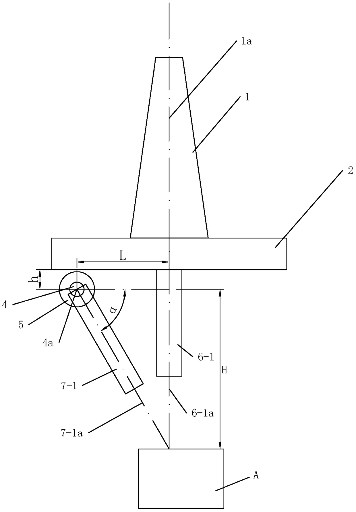
[0015] See figure 1 , the present embodiment has a taper handle 1, and a support plate 2 is provided at the bottom of the taper handle 1, and No. 1 main observation device 6-1 is fixed on the support plate 2, and No. 1 main observation device 6-1 is a built-in CCD digital camera telescope , its collimation axis is called No. 1 principal observation line 6-1a, No. 1 principal observation line 6-1a coincides with the centerline 1a of the taper handle 1, and the support plate 2 is provided with a positioning device capable of rotating around its own axis. Axis 4, axis line 4a of positioning axis 4 is perpendicular to No. 1 main observation line 6-1a in space, and No. 1 sub-observation device 7-1 is fixed on positioning shaft 4, No. 1 sub-observation device 7-1 is a laser, Its optical axis is called the No. 1 auxiliary observation line 7-1a, and the No. 1 auxiliary observation line 7-1a perpendicularly intersects with the axis line 4a of the positioning axis 4. The No. 1 main obse...

Embodiment 2

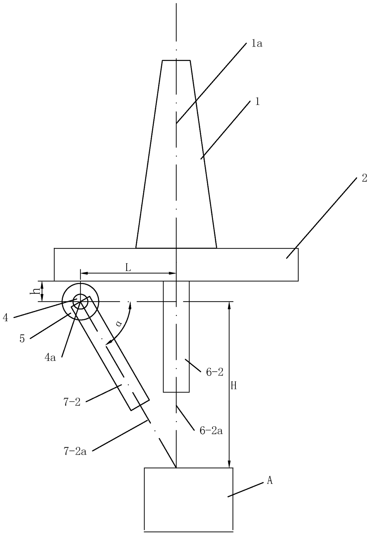
[0019] See figure 2 , the present embodiment has a taper handle 1, and a support plate 2 is provided at the bottom of the taper handle 1, and No. 2 subjective observation device 6-2 is fixed on the support plate 2. No. 2 subjective observation device 6-2 is a laser, and its optical axis It is called the No. 2 subjective observation line 6-2a. The No. 2 subjective observation line 6-2a coincides with the center line 1a of the taper shank 1. On the support plate 2, there is a positioning shaft 4 that can rotate around its own axis. The positioning shaft The axis line 4a of 4 is perpendicular to the No. 2 main observation line 6-2a in space, and the No. 2 sub-observation device 7-2 is fixed on the positioning axis 4, and the No. 2 sub-observation device 7-2 is a built-in CCD digital camera telescope. Its collimation axis is called the No. 2 auxiliary observation line 7-2a, and the No. 2 auxiliary observation line 7-2a perpendicularly intersects with the axis line 4a of the posit...

Embodiment 3

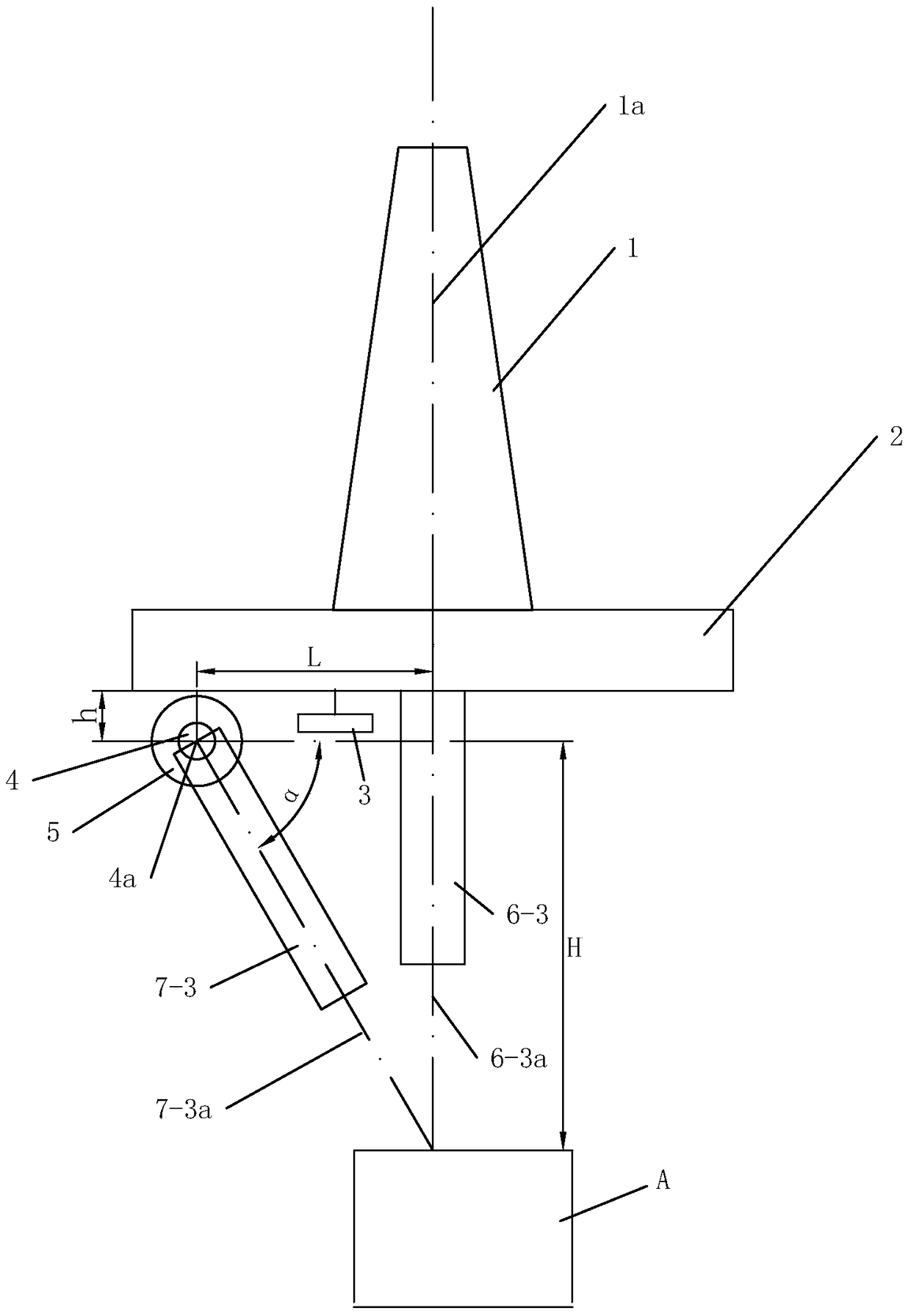
[0023] See image 3 , the present embodiment has a taper handle 1, and a support plate 2 is provided at the bottom of the taper handle 1, and No. 3 subjective observation device 6-3 is fixed on the support plate 2. No. 3 subjective observation device 6-3 is a laser, and its optical axis It is called the No. 3 subjective observation line 6-3a. The No. 3 subjective observation line 6-3a coincides with the center line 1a of the taper shank 1. On the support plate 2, there is a positioning shaft 4 that can rotate around its own axis. The positioning shaft The axis line 4a of 4 is perpendicular to the No. 3 main observation line 6-3a in space, and the No. 3 sub-observation device 7-3 is fixed on the positioning axis 4. The No. 3 sub-observation device 7-3 is a laser, and its optical axis is called The No. 3 sub-observation line 7-3a, the No. 3 sub-observation line 7-3a perpendicularly intersects the axis line 4a of the positioning axis 4, the No. 3 main observation line 6-3a and th...


PUM


Abstract

The invention discloses a coordinate measurement apparatus based on a processing center. The apparatus is provided with a taper shank, the bottom of the taper shank is provided with a support plate, a first primary observation apparatus is fixed on the support plate, the first primary observation apparatus is a built-in CCD digital camera telescope, the collimation axis of the first primary observation apparatus is a first primary observation line, the first primary observation line is superposed with the center line of taper shank, the support plate is provided with a positioning shaft capable of rotating around its own axial lead, the axial lead of the positioning shaft is spatially vertical to the first primary observation line, a first secondary observation apparatus is fixed on the positioning shaft, the first secondary observation apparatus is a laser, the optical axis of the first secondary observation apparatus is a first secondary observation line, the first secondary observation line is vertically intersected with the axial lead of the positioning shaft, the first primary observation line and the first secondary observation line are disposed at the same plane, and the support plate is provided with a coding disc. The coordinate measurement apparatus based on the processing center can meet the requirement for distance measurement precision and does not require tedious and time-consuming calibration in advance. Since distance measurement has nothing to do with a light velocity, before application, neither measurement of temperature, air pressure and the like nor meteorological correction is necessary, and the operation is convenient.

Description

technical field [0001] The invention relates to a coordinate measuring device based on a machining center. Background technique [0002] Machining center is the main equipment for processing complex curves and surfaces. To measure some complex and critical surfaces of the workpiece during part processing, the workpiece needs to be moved out of the CNC machine tool, and clamped again after measurement. This will undoubtedly increase the clamping error. [0003] Coordinate measuring devices have been widely used in scientific research and production. At present, non-contact measurement is developing rapidly. The triangulation method is a commonly used ranging principle. The triangulation method is that a beam of laser light is irradiated on the object, and part of the diffusely reflected laser light is imaged on the photoelectric detection device through a prism. The triangulation method requires many positioning parameters in the application, and it is very cumbersome and...

Claims


Application Information

Patent Timeline
Patent Type & Authority Patents(China)
IPC IPC(8): G01B11/00
Inventor 刘浏范真
Owner JIANGSU UNIV OF TECH
Learn More