Multi-parameter remote monitoring tobacco curing barn

A technology for remote monitoring and flue-curing rooms, applied in the field of flue-curing rooms, can solve the problems of increasing the cost of baking in the flue-curing rooms, affecting the surrounding environment of the flue-curing rooms, and low heat energy utilization, so as to improve the dehumidification effect, improve the cleanliness, and increase the area Effect

Inactive Publication Date: 2016-07-20
GUANGDONG BRANCH OF CHINA TOBACCO GENERAL
View PDF5 Cites 2 Cited by
  • Summary
  • Abstract
  • Description
  • Claims
  • Application Information

AI Technical Summary

Problems solved by technology

The existing tobacco flue-cured room basically adopts the method of setting the dehumidification exhaust port of the flue-cured room to directly discharge the hot and humid air, so that the heat energy is discharged together, resulting in a large amount of waste of heat energy, and the utilization rate of heat energy is low. The cost of baking, and the exhausted hot air will affect the surrounding environment of the tobacco curing room

Method used


Image

  • Multi-parameter remote monitoring tobacco curing barn
  • Multi-parameter remote monitoring tobacco curing barn
  • Multi-parameter remote monitoring tobacco curing barn

Examples


Embodiment 1

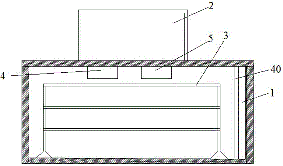
[0090] Such as Figure 5 As shown, the indoor unit 4 includes an air inlet 11, an air outlet 12, an exhaust fan 13, an indoor unit heat exchanger 14, a sump 15 placed below the indoor unit heat exchanger, and a drain pipe 16 connected to the sump.

[0091] Wherein, the heat exchanger 14 of the indoor unit is connected with the outdoor unit, and the heat exchanger 14 of the indoor unit is placed between the air inlet and the air outlet. Several first fins 142 for heat exchange with air.

[0092] Wherein, the condensing pipe 141 is a circuitous bent pipe structure, and the two ends of the condensing pipe 141 are connected with the outdoor unit, and the refrigerant circulates between the condensing pipe 141 and the outdoor unit, and flows in the part of the condensing pipe located at the first fin 142 Carry out gasification, absorb the heat of the surrounding air and the first fins 142, and at the same time, the first fins 142 also rapidly exchange heat with the surrounding air,...

Embodiment 2

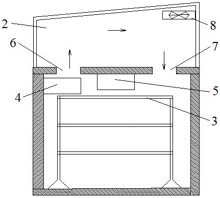
[0095] This embodiment is the second embodiment of the present invention, and the difference from Embodiment 1 lies in the indoor unit heat exchanger 14, such as Image 6 As shown, the first fin 142 is an arc structure, and the concave surface of the arc structure is opposite to the air inlet, so that the effective area of ​​heat exchange of the first fin can be increased without increasing the internal space of the indoor unit. . It should be noted that the arrangement of the first fin 142 in an arc-shaped structure is only preferred, and not the only shape.

[0096] In order to reduce the wind pressure loss inside the indoor unit and reduce the load of the exhaust fan, the first fins 142 are provided with through holes. Under the premise of wind pressure loss, the contact time between the air and the heat exchanger 14 of the indoor unit is increased to improve the dehumidification effect.

[0097] In addition, in order to increase the heat dissipation area, several second ...


PUM


Abstract

The invention relates to the technical field of tobacco curing barns, in particular to a multi-parameter remote monitoring tobacco curing barn. The multi-parameter remote monitoring tobacco curing barn comprises a heating device and a tobacco hanging rack which are arranged in the tobacco curing barn, wherein a circulation greenhouse is arranged outside the tobacco curing barn and communicated with the inside of the tobacco curing barn; an indoor unit and an outdoor unit are further arranged inside the tobacco curing barn and connected, and a gas outlet of the indoor unit is communicated with the circulation greenhouse; a circulation fan is arranged in the circulation greenhouse; a light-transmitting panel is arranged at the top of the circulation greenhouse and forms an included angle being 15-30 degrees with the horizontal plane. Space of the tobacco curing barn is saved, the heat utilization rate is high, and only water is discharged instead of fragrance.

Description

technical field [0001] The invention relates to the technical field of a tobacco flue-cured room, and more specifically, to a multi-parameter remote monitoring tobacco flue-cured room. Background technique [0002] The flue-cured tobacco room is an indispensable basic equipment in the production of flue-cured tobacco. After the tobacco leaves are baked and prepared in the flue-cured room, they will show the unique color, aroma, taste and shape of flue-cured tobacco, and become high-quality raw materials that meet the needs of the cigarette industry. The basic principle is that after the tobacco leaves are heated, the water in the tobacco leaves is discharged, and the water is vaporized and then discharged out of the flue-curing room, so that the tobacco leaves are yellowed and dried. [0003] The existing tobacco flue-cured room is generally equipped with a heating room, which occupies a relatively large area in the flue-cured room, has a low utilization rate of heat energy...

Claims


Application Information

Patent Timeline
Patent Type & Authority Applications(China)
IPC IPC(8): A24B3/10A24B3/04A24B1/02A24B3/12
CPCA24B3/10A24B1/02A24B3/04A24B3/12
Inventor 陈泽鹏
Owner GUANGDONG BRANCH OF CHINA TOBACCO GENERAL
Why Eureka
Try Eureka