
3D printing-based microfluidic chip fixture experiment platform

A microfluidic chip and experimental platform technology, applied in the field of microfluidics, can solve the problems of cumbersome and time-consuming connection processes, and achieve the effects of guaranteed connection quality, simple design, low-cost and fast processing

Active Publication Date: 2016-07-20
BEIJING UNIV OF CHEM TECH
View PDF12 Cites 10 Cited by
  • Summary
  • Abstract
  • Description
  • Claims
  • Application Information

AI Technical Summary

Problems solved by technology

[0004] In order to overcome the problem that the connection tube of the microfluidic chip in the existing laboratory work relies on the experience of the experimenter, takes a long time and the connection process is cumbersome, the present invention provides a microfluidic chip fixture experiment platform based on 3D printing, which is based on 3D printing The microfluidic chip fixture experimental platform can not only help experimenters quickly connect and complete the connecting tubes entering and leaving the microfluidic chip, but also ensure the quality of the connection, and the operation is simple and easy

Method used


Image

  • 3D printing-based microfluidic chip fixture experiment platform

Examples


Embodiment Construction

[0014] The present invention will be further described below in conjunction with the accompanying drawings and embodiments.

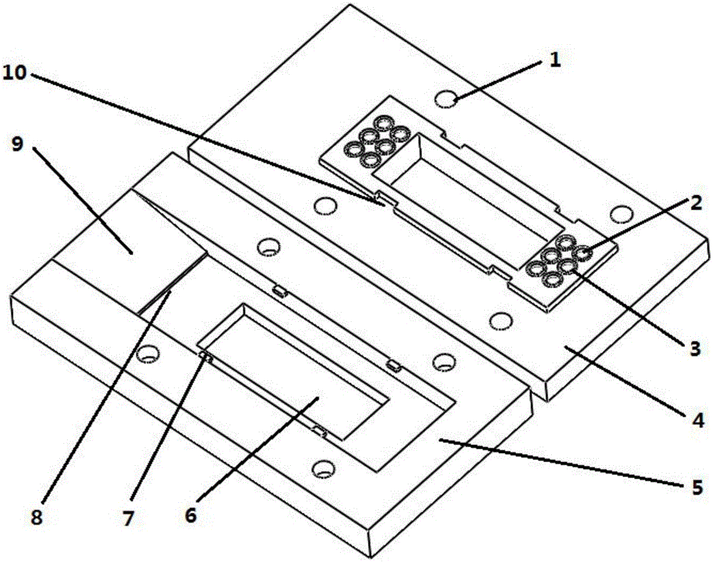
[0015] exist figure 1 Among them, 3D printing is used to manufacture the designed structure, the cover plate (4) is provided with a sealing ring (3), and the sealing ring of the material that is not easily corroded by the fluid used in the experiment is installed at the installation position, and the connecting pipe is installed at the position of the connecting pipe insertion port (2) , the base plate (5) is aligned with the cover plate (4), and the rectangular protrusion (7) is aligned with the rectangular groove (10); after the bolt is connected to the bolt connection hole (1), the base plate (5) and the cover plate (4) ) phase is fixed; during the experiment, enter the microfluidic chip from the slope type microfluidic chip insertion port (9), use the left and right positioning cards (8) to locate, and the rectangular window (6) can observe the flui...


PUM


Abstract

The invention discloses a 3D printing-based microfluidic chip fixture experiment platform. A base plate and a cover plate are two main structures of an experiment platform and are connected through a bolt, wherein rectangular windows of the same size, four bolt through holes and four rectangular bulge positioning settings are respectively reserved in the centers of the base plate and the cover plate; a slope type microfluidic chip insertion port is formed in the base plate, and a left positioning clamp station and a right positioning clamp station are arranged in the base plate; six connecting tube insertion ports and a seal ring mounting position are respectively distributed on each of the left side and the right side of the cover plate. The rectangular windows of the same size, the four bolt through holes and the four rectangular bulge positioning settings are respectively reserved in the centers of the base plate and the cover plate; the slope type microfluidic chip insertion port is formed in the base plate, and the left positioning clamp station and the right positioning clamp station are arranged in the base plate; six connecting tube insertion ports and the seal ring mounting position are respectively distributed on each of the left side and the right side of the cover plate, so that the 3D printing-based microfluidic chip fixture experiment platform is suitable for experimental detection of all types of microfluidic chips and the laboratory use, and can achieve the purposes of rapid processing, low manufacturing cost, simple and convenient operation, and effect improvement of experimental connecting tubes.

Description

technical field [0001] The invention relates to a microfluidic chip fixture experiment platform based on 3D printing. Specifically, 3D printing technology is applied to the production of the microfluidic experimental platform, so as to realize rapid processing of the experimental platform, reduce production costs, and be easy to operate. The purpose of the fixture experiment platform is applicable to various biomedical detection and chemical analysis applications using microfluidic chips, and belongs to the field of microfluidic technology. Background technique [0002] 3D printing is a kind of rapid prototyping technology, and its core principle is: "Layered manufacturing, layer by layer superposition". The printing material of the 3D printer is the raw material of the device, such as metal, ceramics, plastic, sand, etc. The specific implementation process is to use computer-aided design or modeling software to model the object, and then divide the model into layer-by-laye...

Claims


Application Information

Patent Timeline
IPC IPC(8): B01L3/00
CPCB01L3/502715B01L2200/027
Inventor 范一强王玫张亚军
Owner BEIJING UNIV OF CHEM TECH
Learn More