Strip-mode laser scanning path planning method

A technology of laser scanning path and scanning path, which is applied in the field of additive manufacturing, can solve the problem of continuous opening and closing of lasers, and achieve the effect of ensuring the forming quality, improving the quality of parts, and prolonging the service life

Active Publication Date: 2016-07-20
XIAN BRIGHT ADDTIVE TECH CO LTD
View PDF1 Cites 16 Cited by
  • Summary
  • Abstract
  • Description
  • Claims
  • Application Information

AI Technical Summary

Problems solved by technology

[0006] The purpose of the present invention is to provide a strip-type laser scanning path planning method, which solves the problem that the existing strip-type laser scanning method causes the laser to be continuously switched on and off due to the short path near the profile boundary

Method used


Image

  • Strip-mode laser scanning path planning method

Examples


Embodiment Construction

[0018] Combine below Attached drawing The present invention will be described in detail with specific embodiments.

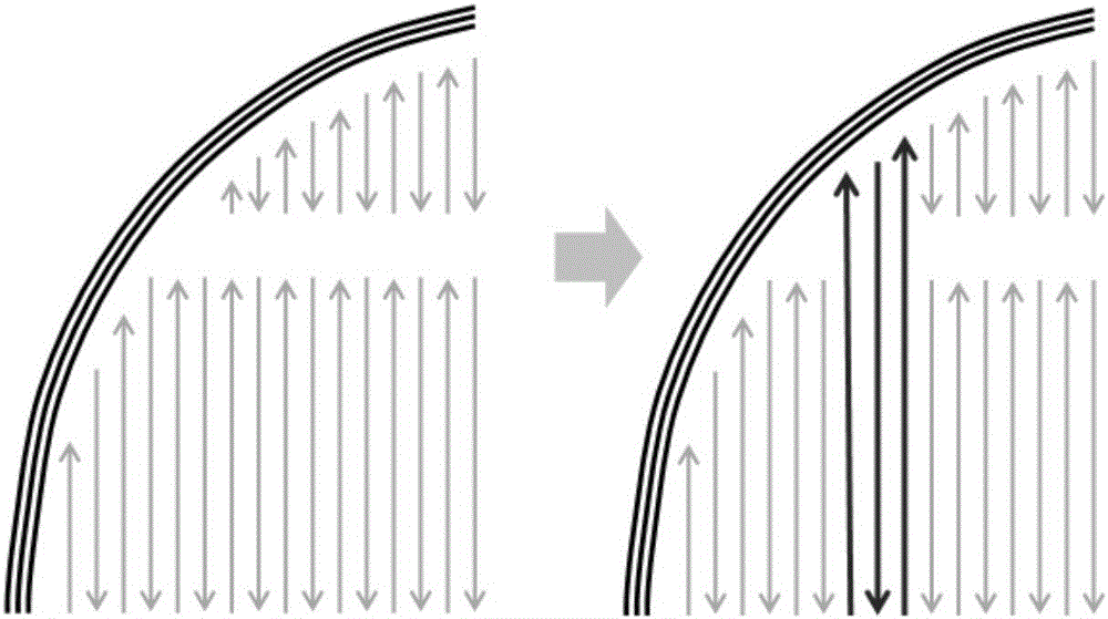
[0019] The present invention is a strip-type laser scanning path planning method, which merges the too short path in each strip zone of the single-layer section of a part with the scanning path in the adjacent zone and the scanning path located on the same path, wherein, in each strip zone The adjacent scanning path directions of are the same or opposite; the specific implementation steps are as follows:

[0020] Step 1: Input the slice files of each layer of the part 3D model, divide each layer of the part into strips according to the structural characteristics of the part, and plan the parallel line scan path for each strip zone;

[0021] Step 2: Read in the user-defined shortest path length and record it as L, where L is less than or equal to the width of a single strip area

[0022] Such as figure 1 As shown, step 3: Using L in step 2 as the reference, starting ...


PUM


Abstract

The invention discloses a strip-mode laser scanning path planning method. The method includes the step that an excessively short path in each strip partition of a part single-layer section is combined with a scanning path, located on the same path with the excessively short path, in an adjacent partition. The paths are selectively combined so that the problem that when a laser device is continuously switched on or off in the scanning process when encountering excessively short paths, and accordingly stress on a part contour boundary is not uniform can be effectively solved. The service life of the laser device is prolonged while the quality of a part is improved. Meanwhile, a user can set a shortest path length parameter by himself or herself according to characteristics of the part to be machined, and part forming quality is guaranteed.

Description

technical field [0001] The invention belongs to the technical field of additive manufacturing, and relates to a strip-type laser scanning path planning method. Background technique [0002] Additive manufacturing technology is based on three-dimensional CAD model data, by adding materials and manufacturing them layer by layer. It is based on the computer three-dimensional design model, through the software layered discrete and numerical control forming system, the material is piled up layer by layer with high-energy beams, and finally superimposed and formed to manufacture physical products. [0003] There are many methods of additive manufacturing, which are mainly divided into manufacturing methods based on powder feeding methods and powder spreading methods. The manufacturing method based on the powder spreading method includes the selective laser melting technology. The processing process is as follows: first design the three-dimensional solid model of the part on the c...

Claims


Application Information

Patent Timeline
Patent Type & Authority Applications(China)
IPC IPC(8): B29C67/00B33Y50/02
CPCB33Y50/02
Inventor 杨东辉薛蕾
Owner XIAN BRIGHT ADDTIVE TECH CO LTD
Why Eureka
Try Eureka