Stabilizer

A stabilizer and stabilizer bar technology, which is applied in transportation and packaging, interconnection systems, elastic suspensions, etc., can solve the problems of the driver's stabilization function that cannot be obtained, the inability to increase the up and down stroke of the wheel, etc., and achieve stable posture maintenance , Improve the effect of grounding

Active Publication Date: 2016-07-20
TOYOTA JIDOSHA KK
View PDF8 Cites 4 Cited by
  • Summary
  • Abstract
  • Description
  • Claims
  • Application Information

AI Technical Summary

Problems solved by technology

[0009] However, since the up and down travel of the wheels cannot be increased, it is disadvantageous in situations where road surface following performance of the wheels is required.
[0010] In this way, no matter in the parallel combination or the cross combination, there is a case where a stabilizing function suitable for the driving state of the vehicle or a stabilizing function that meets the driver's wishes cannot be obtained.

Method used


Image

  • Stabilizer
  • Stabilizer
  • Stabilizer

Examples


Deformed example 1

[0126]

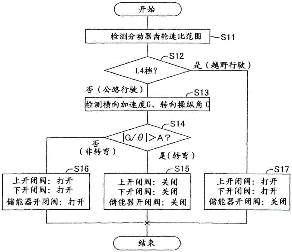
[0127] In the above-described embodiment, the off-road travel determination is performed in steps S11 and S12, but instead of this, a low-speed travel determination may be performed. Figure 6 A valve opening and closing control program according to Modification 1 is shown. In this valve opening and closing control program, the processes of steps S21 and S22 are provided instead of steps S11 and S12 of the embodiment. Hereinafter, for the same processes as those in the embodiment, the same step numbers as those in the embodiment are assigned in the drawings, and descriptions thereof are omitted.

[0128] After starting this routine, the valve ECU 90 reads the vehicle speed V detected by the vehicle speed sensor 91 in step S21, and then determines whether the vehicle speed V is lower than the low speed determination vehicle speed Vref in step S22. The valve ECU advances the process to step S17 when the vehicle speed is lower than the low-speed determination vehicle ...

Deformed example 2

[0130]

[0131] In the above-described embodiment or Modification 1, the valve device 80 is switched to an open and closed state suitable for off-road travel by performing off-road travel determination or low-speed travel determination, but such a configuration is not essential. In Modification 2, a configuration is adopted in which the open and closed state of the valve device 80 is switched between two states only depending on whether the vehicle is turning or not. Valve ECU90 Implementation Figure 7 The valve opening and closing control procedure shown. In the valve opening and closing control program according to Modification 2, steps S11 , S12 , and S17 of the valve opening and closing control program in the embodiment are omitted.

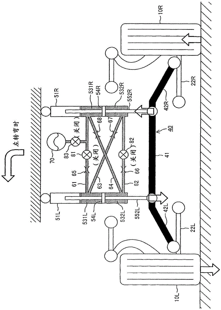
[0132] In Modification 2, as in the embodiment, when the vehicle is turning (S14: YES), the left cylinder 51L and the right cylinder 51R are in a non-expandable state, and the stabilizer bar 40 generates a roll-restraining moment. The to...

Deformed example 3

[0133]

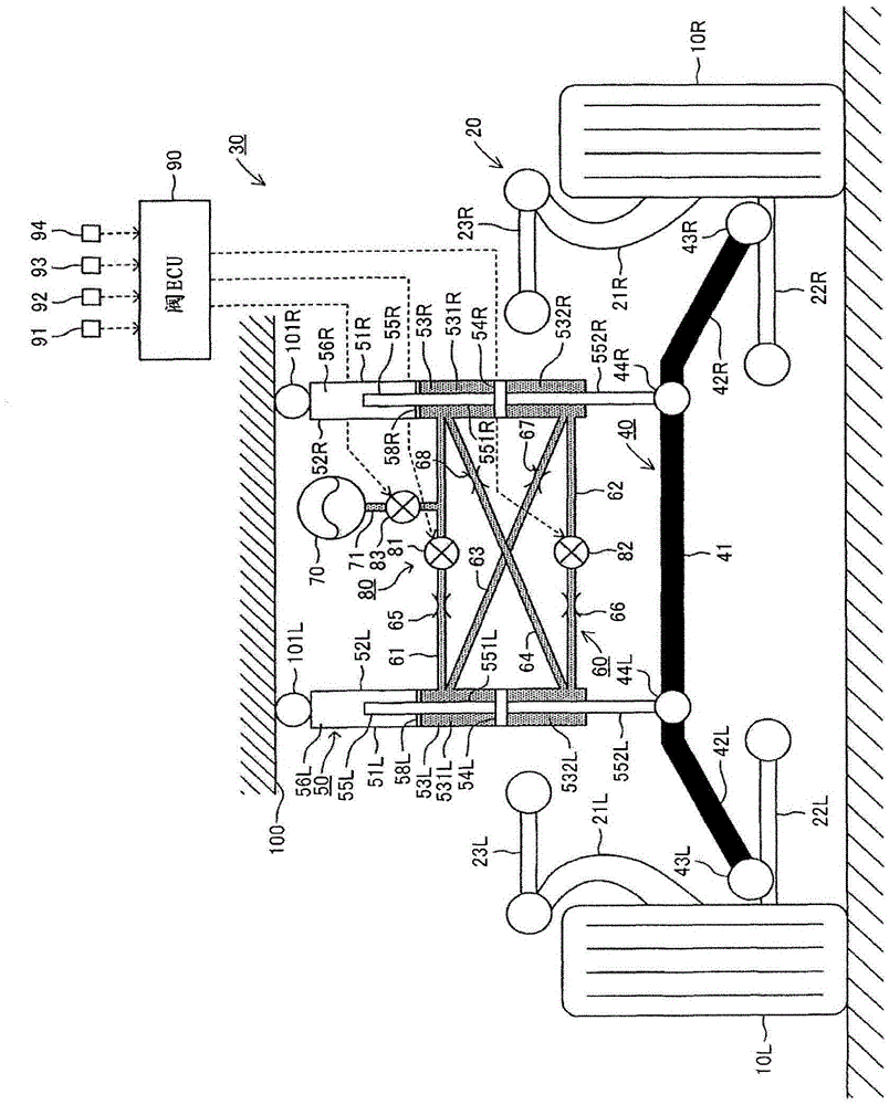
[0134] In the above-mentioned embodiment and the two modified examples, the accumulator 70 and the accumulator on-off valve 83 are provided, and the accumulator on-off valve 83 is switched based on the running state or the driver's operation state (the state of the selector switch). The structure of the open and closed state, but does not have to have such a structure. Figure 8 A schematic configuration of a stabilizer 31 according to Modification 3 is shown. As shown in the figure, the stabilizer 3 according to Modification 3 does not include the accumulator 70 , the accumulator piping 71 , and the accumulator on-off valve 83 provided in the embodiment and Modifications 1 and 2. As shown in FIG.

[0135] In this modified example 3, the valve ECU90 implements Figure 9 The valve control program shown. The valve control program implemented in this modification 3 is provided with the processing of steps S25 and S26 instead of the processing of steps S15 to S17 in t...


PUM


Abstract

The invention provides a stabilizer. The subject of the invention aims at realizing a stabilization function being suitable for the vehicle driving state or according with the hope of a driver. When a vehicle is determined that the vehicle is driven off-road, a valve ECU (90) turns on an upper on-off valve (81) and a lower on-off valve (82) and turns off an energy storage device on-off valve (83). When the vehicle is determined that the vehicle is driven on a road and makes a turn, the valve ECU (90) turns off the upper on-off valve (81), the lower on-off valve (82) and the energy storage device on-off valve (83). When the vehicle is determined that the vehicle does not make a turn, the valve ECU (90) turns on the upper on-off valve (81), the lower on-off valve (82) and the energy storage device on-off valve (83).

Description

technical field [0001] The present invention relates to a stabilizer device including: a stabilizer bar interposed between left and right wheels and a vehicle body; and a cylinder for changing the function of the stabilizer bar. Background technique [0002] Patent Document 1 proposes a stabilizer system in which a left cylinder is arranged vertically between the left end of the stabilizer bar and the left wheel, and a right cylinder is arranged vertically between the right end of the stabilizer bar and the right wheel. device. In this stabilizer, the left and right cylinders are divided into an upper chamber and a lower chamber by a piston, and the upper chamber of the left cylinder communicates with the upper chamber of the right cylinder through an upper communication passage, and the lower chamber of the left cylinder communicates with the right cylinder. The lower chamber communicates with the lower chamber. Hereinafter, the coupling realized by such communication pas...

Claims


Application Information

Patent Timeline
Patent Type & Authority Applications(China)
IPC IPC(8): B60G21/055
CPCB60G21/0553B60G17/0162B60G21/073B60G2202/135B60G2202/413B60G2204/62B60G2204/80B60G2206/0116B60G2400/51B60G2800/012B60G2800/9122B60G21/0558B60G2800/20
Inventor 田畑雅朗福冈孝延
Owner TOYOTA JIDOSHA KK
Why Eureka
Try Eureka