Mobile Side Feed Chain Bulk Stacker

A mobile stacking machine technology, applied in the field of construction machinery, can solve the problems of poor mobility of equipment, low utilization rate of the stockyard, high useless energy consumption, etc., and achieve safe and reliable one machine with multiple functions, adjustable stacking height, and low useless The effect of energy consumption

Active Publication Date: 2018-03-13
WUHAN K CRANE OCEAN ELEVATORING TECH
View PDF7 Cites 0 Cited by
  • Summary
  • Abstract
  • Description
  • Claims
  • Application Information

AI Technical Summary

Problems solved by technology

[0002] Professional large-scale bulk material stacking and storage generally use professional large-scale bulk material stacking equipment such as bucket wheel machines and cantilever stackers. However, for the problem of bulk material stacking in small bulk cargo terminals or in warehouses, loaders and dump trucks are currently used. The accumulation method of various intermittent bulk materials combined with the belt conveyor; this type of accumulation process has the following problems: 1. Difficulty in transferring the equipment: due to the large length and size of the belt conveyor, the flexibility of the equipment is poor, and the unloading of the dump truck The platform will also cause difficulties in the loading and unloading of vehicles in the yard, making the operation efficiency low; 2. The unloading platform leads to high useless energy consumption: if there is a material transfer link, an unloading platform is used, so that each time the dump truck lifts its own weight, it will cause Useless energy consumption; 3. The height of the bulk material stack is limited: the height of the small-scale transfer equipment with flexible equipment is limited, which makes the utilization rate of the stockyard low, especially in the case of large inventory, the problem of site utilization rate is more prominent; 4 , There are potential safety hazards, and accidents of dump trucks and excavators slipping from the stockpile frequently occur
For the loading and unloading process of bulk cargo, the combination of dump truck, unloading platform, receiving hopper, fixed belt conveyor and barge is currently used. Problems such as high energy consumption during the process of unloading trucks climbing onto the unloading platform, time-consuming waiting for the system during barge movement during loading, and fuel emission pollution, etc.
[0003] In view of the above-mentioned problems of bulk material stacking height and loading on ships or trucks, the application number of the Chinese patent "A New Tire-Type Mobile Stacking Device": 2010102371370, "A Bulk Cargo Loading System for Trains" application number: 2014207415203 and " Simple Mobile Loading Ship System" application number: 2014201892675 The invention content does not involve the solution to the flexibility of equipment transfer, higher material stacking height requirements, especially the low-level direct unloading technology on the ground without dump truck unloading platform

Method used


Image

  • Mobile Side Feed Chain Bulk Stacker
  • Mobile Side Feed Chain Bulk Stacker
  • Mobile Side Feed Chain Bulk Stacker

Examples


Embodiment 1

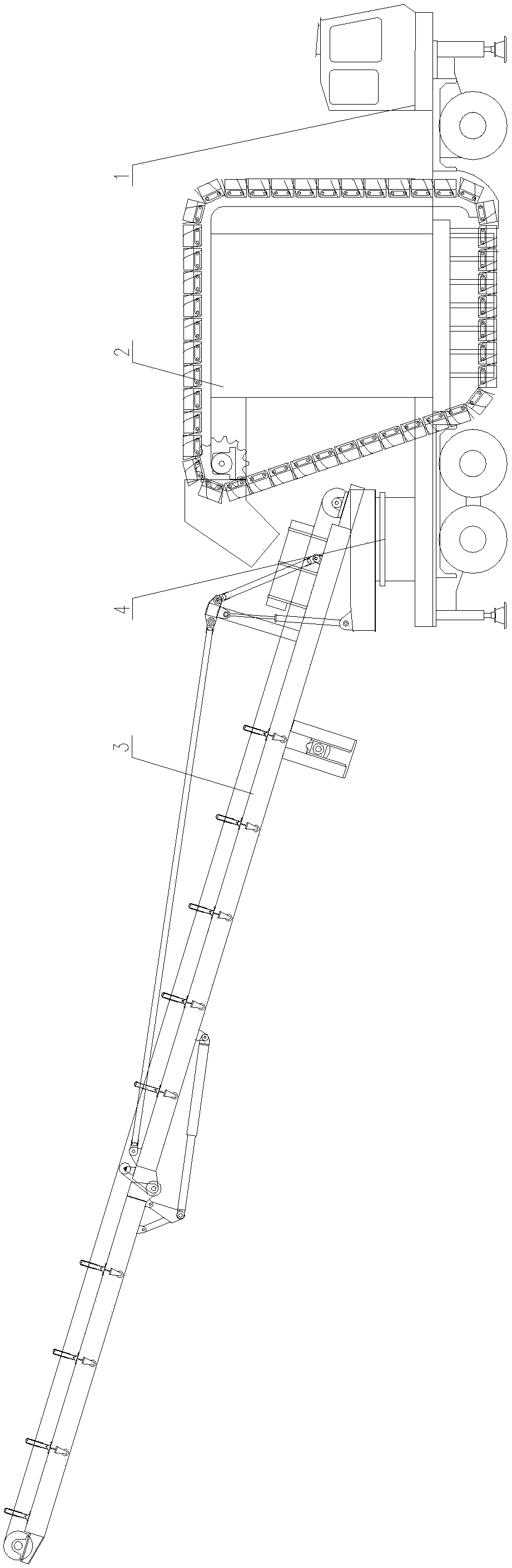
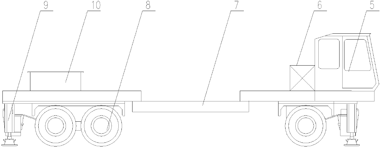
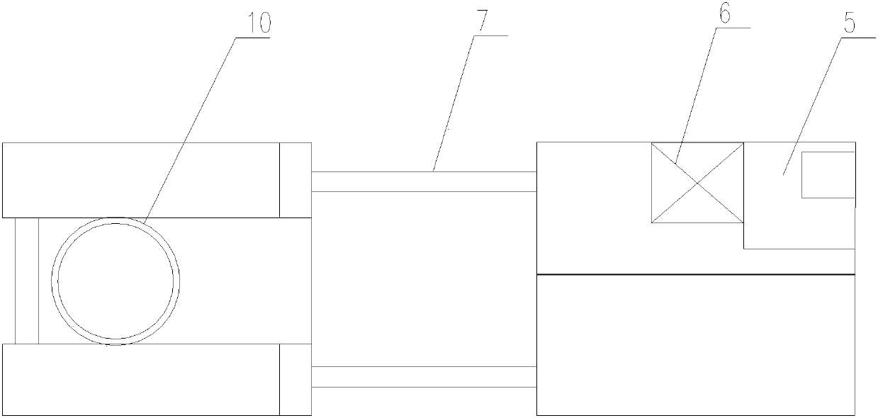
[0040] Such as figure 1As shown, the flow type side feeding chain type bulk material stacker 42 includes a car body assembly 1 , a material transfer device 2 , a folding belt conveyor 3 , and a rotary mechanism 4 . The car body assembly 1 is used as the carrier of the whole machine equipment, and is used for installing the transfer material device 2, the folding belt conveyor 3 and the turning mechanism 4 and the walking and transition of the whole machine. The transfer material device 2 is located in the middle of the car body assembly 1 and is fixedly connected with the vehicle frame 7. Its horizontal section is combined with the bottom side plate of the conveying device support frame 22 to form a material receiving trough 23, which is used to accept the unloading of the dump truck 43, and The material is lifted and transported to the receiving hopper 15 of the folding belt conveyor 3 by means of the endless conveying device. The rotary platform 17 of the rotary mechanism 4...

Embodiment 2

[0049] Such as Figure 12 As shown, the flow type side feeding chain type bulk material stacker 42 includes a car body assembly 1, a transfer material device 2, a folding belt conveyor 3, and a rotary mechanism 4. The car body assembly 1 is used as the carrier of the whole machine equipment, and is used for installing the transfer material device 2, the folding belt conveyor 3 and the turning mechanism 4 and the walking and transition of the whole machine. The transfer material device 2 is located in the middle of the vehicle body assembly 1 and is fixedly connected to the vehicle frame 7. Its material conveying horizontal section is combined with the bottom side plate of the conveying device support frame 22 to form a material receiving trough 23, which is used to receive the unloading of the dump truck 43. , and the material is lifted and transported to the receiving hopper 15 of the folding belt conveyor 3 through the endless conveying device. The rotary platform 17 of the...

Embodiment 3

[0056] Such as Figure 15 As shown, the flow type side feeding chain type bulk material stacker 42 includes a car body assembly 1, a transfer material device 2, a folding belt conveyor 3, and a rotary mechanism 4. The car body assembly 1 is used as the carrier of the whole machine equipment, and is used for installing the transfer material device 2, the folding belt conveyor 3 and the turning mechanism 4 and the walking and transition of the whole machine. The transfer material device 2 is located in the middle of the vehicle body assembly 1 and is fixedly connected to the vehicle frame 7. Its material conveying horizontal section is combined with the bottom side plate of the conveying device support frame 22 to form a material receiving trough 23, which is used to receive the unloading of the dump truck 43. , and the material is lifted and transported to the receiving hopper 15 of the folding belt conveyor 3 through the annular scraper conveying device. The rotary platform 1...


PUM


Abstract

The invention discloses a flowing type side-feeding chained bulk material stacking machine. A vehicle body assembly as a supporting body of the whole machine is in contact with the ground. A folding belt conveyor is mounted on a hinged support of the folding belt conveyor of a rotary platform at the tail of the vehicle body, the rotary platform of a rotary mechanism is mounted on a rotary supporting cylinder at the tail of the vehicle body assembly, and a material transferring device is connected to the middle of the vehicle body assembly through a conveying device supporting rack. The flowing type side-feeding chained bulk material stacking machine is suitable for stacking, shipping and loading bulk materials. A dumper, without auxiliary equipment such as an unloading platform, can directly pour materials to a discharge chute of the dumper from the side and finish the stacking operation of materials in different heights through a rotary motion of a rotary device and amplitude and stretch motions of the folding belt conveyor. The flowing type side-feeding chained bulk material stacking machine has the characteristics of compact structure, flexibility in field transfer, good field adaptability and adjustable stacking height.

Description

technical field [0001] The invention relates to engineering machinery, in particular to a flow type side feeding chain type bulk material stacker. Background technique [0002] Professional large-scale bulk material stacking and storage generally use professional large-scale bulk material stacking equipment such as bucket wheel machines and cantilever stackers. However, for the problem of bulk material stacking in small bulk cargo terminals or in warehouses, loaders and dump trucks are currently used. The accumulation method of various intermittent bulk materials combined with the belt conveyor; this type of accumulation process has the following problems: 1. Difficulty in transferring the equipment: due to the large length and size of the belt conveyor, the flexibility of the equipment is poor, and the unloading of the dump truck The platform will also cause difficulties in the loading and unloading of vehicles in the yard, making the operation efficiency low; 2. The unload...

Claims


Application Information

Patent Timeline
Patent Type & Authority Patents(China)
IPC IPC(8): B65G65/28
CPCB65G65/28
Inventor 杨仲袁建明王贡献
Owner WUHAN K CRANE OCEAN ELEVATORING TECH
Why Eureka
Try Eureka