Supercharge Your Innovation With Domain-Expert AI Agents!

An energy-saving thermal cycle filling machine

A seam filling machine and thermal cycle technology, applied in the direction of roads, road repair, roads, etc., can solve the problem that the heat energy of the seam filling machine cannot be fully covered and circulated, the asphalt or the seam filling glue is heated unevenly, and the work efficiency of the seam filling machine is affected, etc. problem, to achieve the effect of good melting effect, short standby time and compact structure

Active Publication Date: 2018-01-19
ZHONGSHAN YILUMEI ROAD MAINTENANCE TECH CO LTD
View PDF7 Cites 0 Cited by
  • Summary
  • Abstract
  • Description
  • Claims
  • Application Information

AI Technical Summary

Problems solved by technology

[0002] The joint filling machine is mainly used for preventive maintenance of road surface diseases, road construction and maintenance of municipal facilities. It usually fills the cracks on the asphalt road surface and the expansion joints reserved on the cement road surface by pouring. The existing The joint filling machines are heated and melted asphalt or joint glue in a static state, so the heating time is long, and the working efficiency of the joint filling machine is affected due to the prolongation of the standby time for the joint filling operation. At the same time, the joint filling machine The heat energy generated cannot be fully covered and circulated, causing the asphalt or joint glue to be heated unevenly, which is not conducive to pouring, and the heat of the fuselage is easy to volatilize, and the burner needs to be in the working state for a long time, which is not energy-saving

Method used


Image

  • An energy-saving thermal cycle filling machine
  • An energy-saving thermal cycle filling machine
  • An energy-saving thermal cycle filling machine

Examples


Embodiment Construction

[0039] The present invention will be further described in detail below in conjunction with the accompanying drawings.

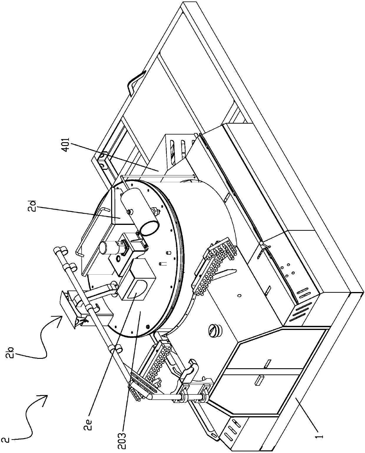
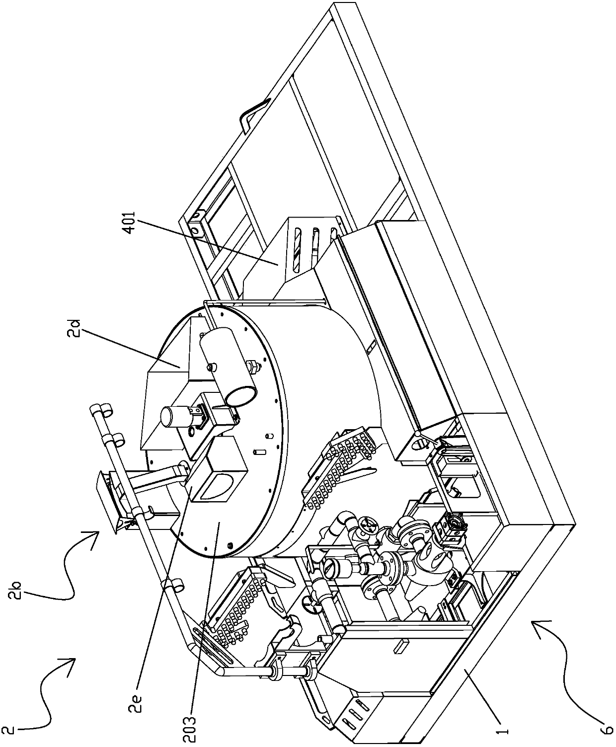
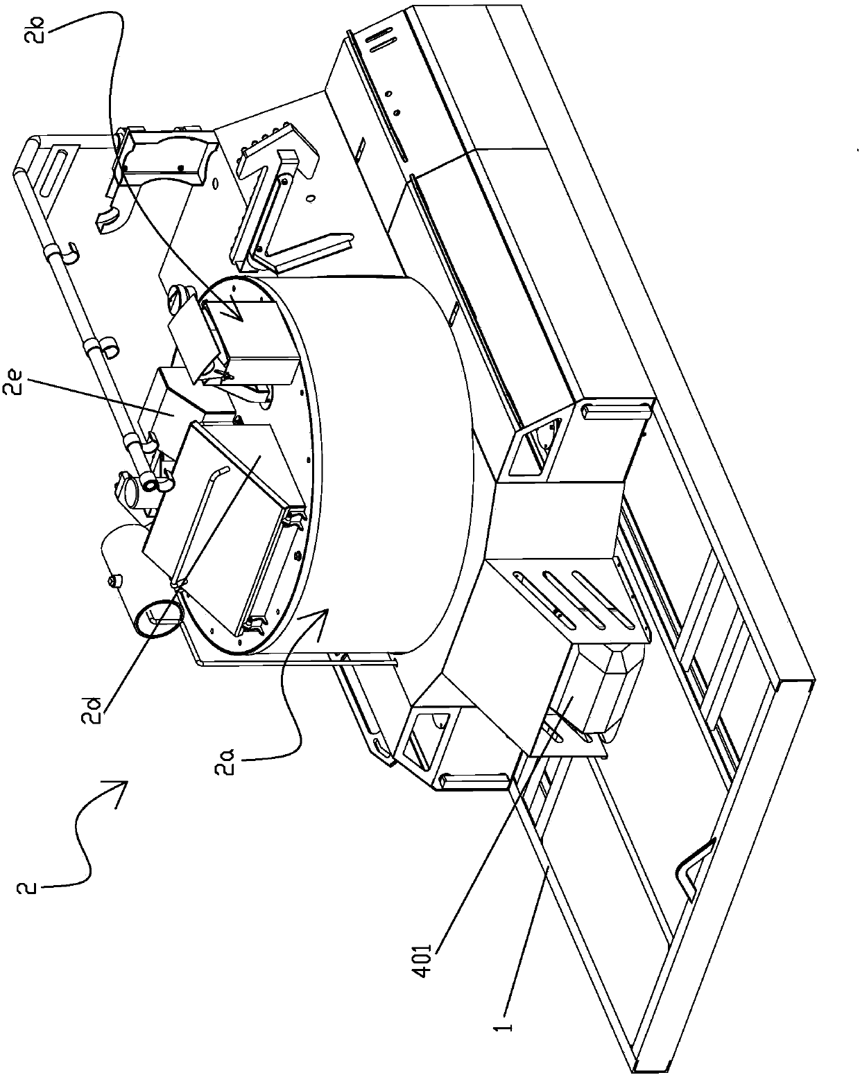
[0040] An energy-saving thermal cycle seam filling machine, comprising a frame 1, the frame 1 is provided with a heating cycle device 2, and the heating cycle device 2 includes a circulating melt chamber 201, and the circulating melt chamber 201 A stirring device 3 for stirring asphalt or joint glue is provided inside, and a temperature control device 4 for controlling the temperature in the cavity is provided on the wall of the circulating molten material chamber 201, and the temperature control device 4 includes a heating gas The burner 401, the lower side of the circulating molten material chamber 201 is provided with a hot gas circulation chamber 402 connected to the burner 401 at one end and capable of storing the gas heated by the burner 401, and the heating cycle The device 2 is provided with a hot gas circulation heating insulation layer 2a for surrou...


PUM


Abstract

The invention discloses energy-saving efficient heat-circulation joint sealing machine which comprises a frame. A heating circulation device is arranged on the frame and comprises a circulation melt cavity, a stirring device for stirring asphalt or joint sealing glue is arranged in the circulation melt cavity, and a temperature control device for controlling the temperature in the circulation melt cavity is arranged on the wall of the circulation melt cavity. The temperature control device comprises a burner which can heat gas. A hot gas circulation cavity capable of storing the gas heated by the burner is arranged on the lower side of the circulation melt cavity. One end of the hot gas circulation cavity is connected with the burner. The heating circulation device is provided with a hot gas circulation heating thermal insulation layer which is used for sealing the circulation melt cavity and the hot gas circulation cavity in a surrounding manner and can allow the hot gas to circulate in the hot gas circulation cavity, the hot gas circulation heating thermal insulation layer is provided with a gas outlet capable of allowing the hot gas in the hot gas circulation cavity to discharge, and the hot gas circulation heating thermal insulation layer is provided with a sealing gas discharge adjusting device which is used for sealing the gas outlet and can control the temperature in the circulation melt cavity by changing the sealing position.

Description

【Technical field】 [0001] The invention relates to a machine device, more specifically to an energy-saving thermal cycle seam filling machine. 【Background technique】 [0002] The joint filling machine is mainly used for preventive maintenance of road surface diseases, road construction and maintenance of municipal facilities. It usually fills the cracks on the asphalt road surface and the expansion joints reserved on the cement road surface by pouring. The existing The joint filling machines are heated and melted asphalt or joint glue in a static state, so the heating time is long, and the working efficiency of the joint filling machine is affected due to the prolongation of the standby time for the joint filling operation. At the same time, the joint filling machine The generated heat energy cannot be fully covered and circulated, causing the asphalt or joint glue to be heated unevenly, which is not conducive to pouring, and the heat of the fuselage is easy to volatilize, an...

Claims


Application Information

Patent Timeline
Patent Type & Authority Patents(China)
IPC IPC(8): E01C23/09
CPCE01C23/0973
Inventor 贾永力姜万双
Owner ZHONGSHAN YILUMEI ROAD MAINTENANCE TECH CO LTD
Features
  • R&D
  • Intellectual Property
  • Life Sciences
  • Materials
  • Tech Scout
  • Unparalleled Data Quality
  • Higher Quality Content
  • 60% Fewer Hallucinations
Learn More