Stability extending device of centrifugal compressor

A centrifugal compressor and an external technology, applied in the field of compressors, can solve the problems of reduced performance of the compressor, unfavorable for popularization and application, complicated processing and manufacturing, etc., achieving small pipeline loss, easy engineering application and popularization, and convenient installation and operation. Effect

Active Publication Date: 2016-07-20
HEFEI GENERAL MACHINERY RES INST
View PDF8 Cites 6 Cited by
  • Summary
  • Abstract
  • Description
  • Claims
  • Application Information

AI Technical Summary

Problems solved by technology

With the self-priming structure of the original centrifugal compressor, the energy injected into the main flow is not enough to improve the internal flow conditions as much as possible, and the stability expansion ability is limited; the Chinese patent document CN101660543A discloses a method for expanding the stability of the passive jet of the rotor blade tip. Through the modification of the fan / compressor casing, a local acceleration zone is formed at the leading edge of the rotor blade tip, so as to achieve an effect similar to that of the rotor blade tip jet. Although it is relatively easy to achieve in terms of structure, due to its overall structure It will not change after manufacture, since the passage structure itself is always in the open state after the manufacture, it will also change the internal flow of the compressor under the stable working condition of the compressor, especially when it is running under various complex working conditions Especially serious, it often causes a large decline in the performance of the compressor; Chinese patent document CN103953560A discloses a compressor stability expansion system and a compressor mechanism applied to the system. The gas collection chamber is complicated to process and manufacture, which is not conducive to popularization and application

Method used


Image

  • Stability extending device of centrifugal compressor
  • Stability extending device of centrifugal compressor
  • Stability extending device of centrifugal compressor

Examples


Embodiment Construction

[0028] The technical solutions in the present invention will be clearly and completely described below in conjunction with the accompanying drawings in the embodiments of the present invention. Based on the embodiments of the present invention, all other embodiments obtained by persons of ordinary skill in the art without making creative efforts belong to the protection scope of the present invention.

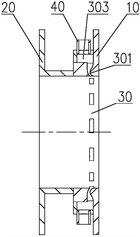
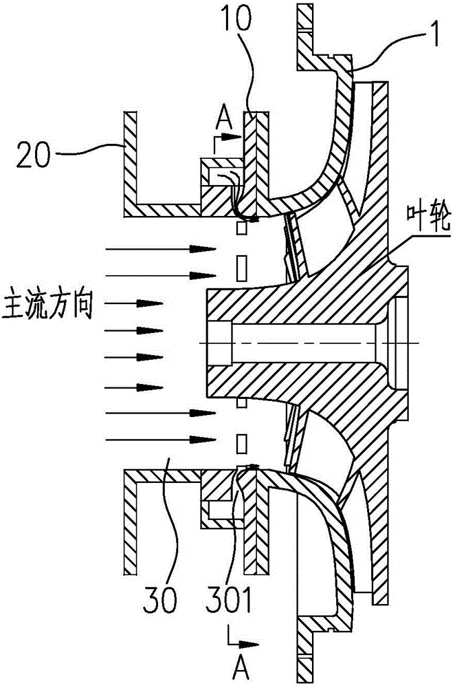
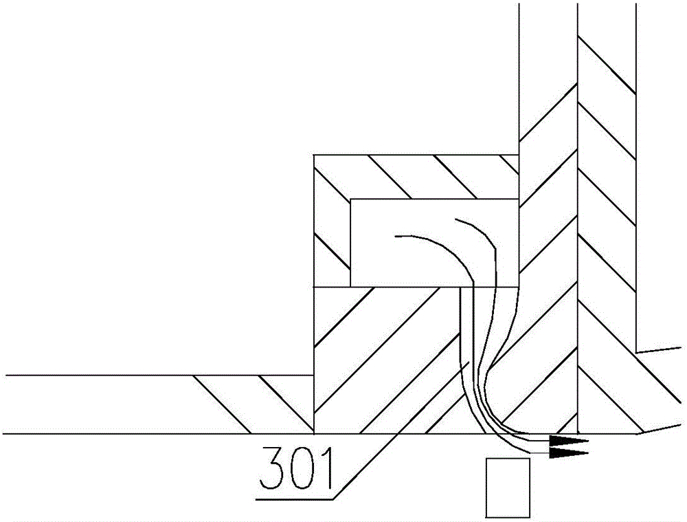
[0029] like figure 1 , 2 As shown, it is a centrifugal compressor stabilizing device, the device is external, and its two sides are respectively provided with the first flange 10 for seamless connection with the front cover plate 1 of the centrifugal compressor and the suction pipe. , the second flange 20, the first flange 10 and the second flange 20 are arranged in parallel, and the middle part of the two flanges is provided with a main flow pipe 30 perpendicular to the flange; the main flow pipe 30 communicates with an air intake duct 40 for external air supply.

[0030] S...


PUM


Abstract

The invention discloses a stability extending device of a centrifugal compressor. The device is external. A first flange plate and a second flange plate which are seamlessly connected to a front cover plate and a suction pipeline of the centrifugal compressor are separately arranged on two sides of the device. The first flange plate and the second flange plate are arranged in parallel, and a main flow pipeline perpendicular to the flange plates is arranged between the two flange plates; and the main flow pipeline communicates with a gas inlet pipeline for external gas supply. A plurality of injection holes are formed in the peripheral direction of an inner wall face of the main flow pipeline, gas collection cavities are formed in the outer wall faces of the injection holes, and connectors which communicate with the gas inlet pipeline are arranged on the gas collection cavities; an external compressed gas flow enters the gas collection cavities from the gas inlet pipeline and then enters the main flow pipeline of the compressor through the injection holes which are formed in the peripheral direction; through the injection holes, gas enters radially and is sprayed out in the tangential direction of the inner surface of a flow path. The stability extending device of the centrifugal compressor is simple in structure and convenient to mount and disassemble, and can effectively expand the operating margin of the centrifugal compressor.

Description

technical field [0001] The invention belongs to the technical field of compressors, and in particular relates to a centrifugal compressor stabilization device. Background technique [0002] As a kind of fluid machinery, centrifugal compressor is widely used in oil refining, chemical industry, metallurgy, refrigeration and air conditioning and other fields. The centrifugal compressor has a certain stable working range. When the compressor operates in an unstable working condition, the performance will be greatly deteriorated, which may further cause the compressor to stall and surge, and even cause the machine to fail to work normally, eventually causing major accidents. Therefore, the development trend of the centrifugal compressor requires it to have a wider working range. [0003] Aiming at the characteristic of centrifugal compressor's stable working range, researchers have conducted many studies, such as expanding its stable working range through compressor inlet guide ...

Claims


Application Information

Patent Timeline
Patent Type & Authority Applications(China)
IPC IPC(8): F04D29/42F04D29/68
CPCF04D29/68F04D29/4213F04D29/684
Inventor 杨启超赵远扬李连生肖军
Owner HEFEI GENERAL MACHINERY RES INST
Why Eureka
Try Eureka