Ballastless track plate seam depth non-destructive detection method and equipment based on vibration

A ballastless track and non-destructive testing technology, applied in measuring devices, instruments, using ultrasonic/sonic/infrasonic waves, etc., can solve problems that are difficult to meet the actual detection

Active Publication Date: 2016-07-20
四川升拓检测技术股份有限公司
View PDF6 Cites 23 Cited by
  • Summary
  • Abstract
  • Description
  • Claims
  • Application Information

AI Technical Summary

Problems solved by technology

[0023] For the detection of the separation depth of the track plate in the above-mentioned prior art, the feeler gauge method, the non-destructive testing method based on ultrasonic waves, and the non-destructive testing method based on shock elastic waves

Method used


Image

  • Ballastless track plate seam depth non-destructive detection method and equipment based on vibration
  • Ballastless track plate seam depth non-destructive detection method and equipment based on vibration
  • Ballastless track plate seam depth non-destructive detection method and equipment based on vibration

Examples


Embodiment 1

[0056] like Figure 9 , a vibration-based non-destructive detection method for the separation depth of ballastless track slabs. Departure depth detection, the detection method includes the following steps in order:

[0057] S1, fixing the excitation recording element on the track plate to be detected;

[0058] S2. Using an excitation device to vibrate the track plate, so that the track plate generates a vibration signal;

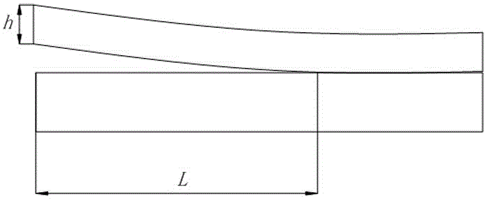
[0059] S3. Obtain the first-order natural frequency f in the vibration signal on the spectrum diagram obtained by the excitation signal processing element 1 or the second-order natural frequency f 2 , and the depth of the track slab gap is obtained by the following formula: Among them, L is the depth of the track slab, ρ is the density of the track slab, h is the thickness of the track slab, E is the dynamic elastic modulus of the track slab, A is the area of ​​the vibration section of the track slab, and I is the moment of inertia of the track slab sec...

Embodiment 2

[0070] This embodiment is further limited on the basis of Embodiment 1, as a further technical solution of the vibration-based non-destructive detection method for the separation depth of ballastless track slabs:

[0071] In order to simplify the calculation of the above formula and improve the detection accuracy of the gap, the value of E or the value of E / ρ is obtained in the following way:

[0072] E=E c / 0.83, where E c is the elastic modulus of track slab concrete, and 0.83 is the corrected value obtained through data fitting. For C55 concrete, it can be 35.5GPa; for C60 concrete, it can be 36.0GPa;

[0073] As a technical solution that can be directly tested on site:

[0074] Among them, f d is the natural frequency f on the spectrogram 1 The reflection frequency corresponding to the longitudinal wave resonance in the corresponding period is also called the excellent frequency.

[0075] Since different track plates have different E values ​​and ρ values, f d It i...

Embodiment 3

[0081] This embodiment further defines the device on the basis of Embodiment 1: As a further technical solution of the vibration-based ballastless track plate separation depth non-destructive testing device, the data connection is a wire electrical connection, wireless Any of the signal data connections. The above data connection forms can be freely selected according to the detection conditions or cost.


PUM

PropertyMeasurementUnit
Diameteraaaaaaaaaa
Diameteraaaaaaaaaa

Abstract

The present invention discloses a ballastless track plate seam depth non-destructive detection method and equipment based on vibration. For the problem that a feeler gauge method, a non-destructive detection method based on ultrasonic wave and a non-destructive detection method used in detecting a ballastless track plate seam depth have large limitation and the need of actual detection is difficult to satisfy in the prior art, the scheme provides the method and the equipment and aims to use an exciting device to allow a track plate edge to generate tiny vibration, and through analyzing the spectral characteristics of the vibration, the depth of a track plate seam is visually, conveniently, efficiently and accurately measured.

Description

technical field [0001] The invention relates to the technical field of safety detection in the railway industry, in particular to a vibration-based non-destructive detection method and equipment for the separation depth of ballastless track slabs, specifically a method and equipment for detecting the separation depth of ballastless track slab edges by using tiny induced vibrations Non-destructive testing methods and equipment. Background technique [0002] The ballastless track cancels the sleeper and ballast bed of the traditional ballast track, uses the prefabricated reinforced concrete slab to directly support the rail, and fills the CA mortar or self-compacting concrete cushion between the track slab and the concrete foundation plate, which is a new comprehensive Supported slab track structure. It has the following advantages: good stability and smoothness; low building height and light weight, which can reduce the second phase load of bridges and reduce tunnel clearanc...

Claims


Application Information

Patent Timeline
IPC IPC(8): G01B17/00
CPCG01B17/00
Inventor 吴佳晔李振廷张志远朱纪刚姚鑫吴曾炜
Owner 四川升拓检测技术股份有限公司
Why Eureka
Try Eureka