
System and method for testing dynamic characteristics of helical spring

A helical spring and dynamic characteristic technology, applied in the field of dynamic characteristic testing, can solve problems such as inability to obtain inherent characteristic parameters of the spring, inaccurate vibration characteristics of the air spring, and inability to reflect the vibration characteristics of the spring, etc., to achieve simple clamping process and wide application range Wide, easy to disassemble effect

Active Publication Date: 2016-07-20
TONGJI UNIV
View PDF5 Cites 13 Cited by
  • Summary
  • Abstract
  • Description
  • Claims
  • Application Information

AI Technical Summary

Problems solved by technology

It uses a mass block to adjust the spring precompression value through the size of the mass block. The procedure is cumbersome and not accurate enough
Test the displacement and acceleration at one end of the air spring. Due to the overall shape and height of the spring, only the vibration response at one end means that the vibration characteristics of the entire air spring are inaccurate and oversimplified.
The defects of this patent include: only for the air spring system, the adjustment of precompression is not accurate enough, the test target is only the displacement and acceleration response of one end of the air spring, which cannot reflect the overall vibration characteristics of the spring, and cannot obtain the spring dynamic stiffness value. The inherent characteristic parameters of the spring cannot provide the required dynamic characteristic parameters for further analysis and research of the mechanical structure installed.

Method used


Image

  • System and method for testing dynamic characteristics of helical spring
  • System and method for testing dynamic characteristics of helical spring
  • System and method for testing dynamic characteristics of helical spring

Examples


Embodiment 1

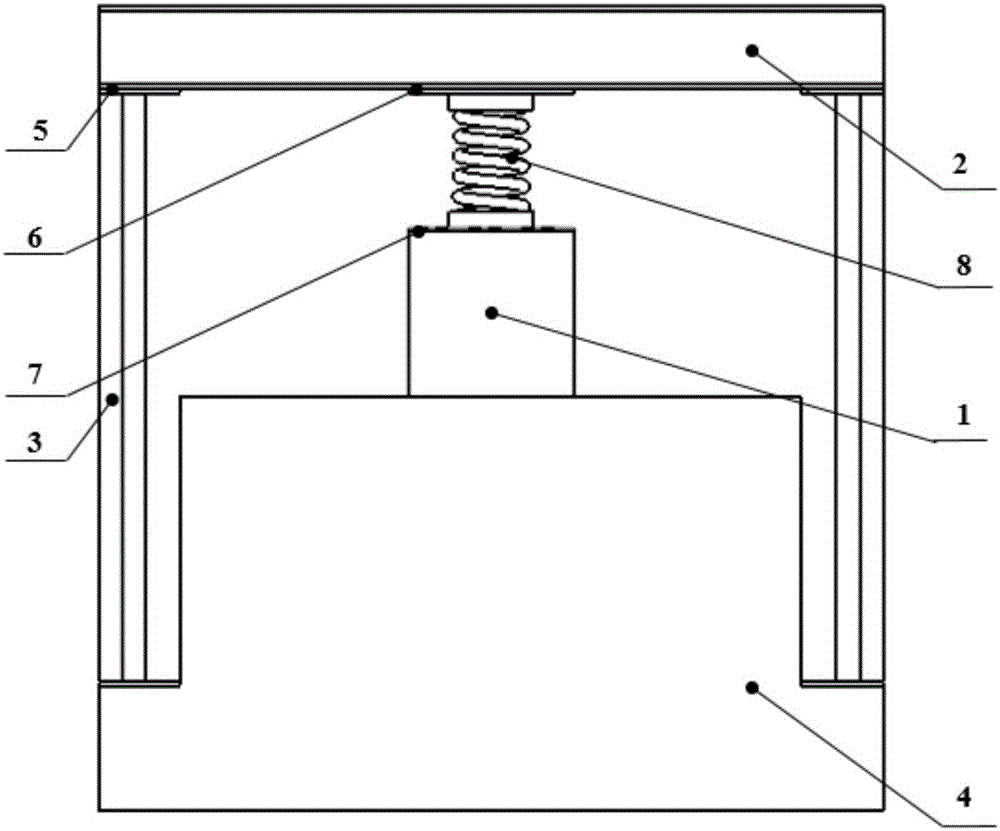
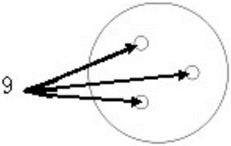
[0046] A helical spring dynamic characteristic testing system, used to test the dynamic performance of helical spring, the working principle diagram is as follows figure 1 As shown, the schematic diagram of the composition structure is shown in Figure 2-1 As shown, it includes a base 4, a vertical vibrating table 1, a displacement sensor, a special fixture, two sets of force sensors 9 for contacting the two ends of the coil spring 8 to be tested, and a spring fixed on each coil of the coil spring 8 to be tested. An acceleration sensor and a signal acquisition and processing device connected with each sensor. Among them, the vertical vibrating table 1 is fixed on the base 4, the exciting end of the vertical vibrating table 1 is fixed with the first bearing platform 7 by bolts, the special fixture includes the beam 2 and the side beam 3, and the beam 2 is welded by two H-shaped steel 21 in parallel Formed on it, the second load-bearing platform 6 is fixed by bolts, the first l...


PUM


Abstract

The invention relates to a system for testing the dynamic characteristics of a helical spring. The system comprises a pedestal, a vertical vibration bench, a displacement sensor, a spring clamp, two sets of force sensors contacted with two ends of the helical spring to be tested, accelerometers fixed to each wound spring of the helical spring to be tested, and signal acquisition and processing devices connected with each sensor, wherein the vertical vibration bench and the spring clamp are fixed on the pedestal, a first load-bearing platform and a second load-bearing platform are respectively arranged on the excitation end of the vertical vibration bench and the spring clamp, the helical spring to be tested is pre-compressed by adjusting the distance between the first load-bearing platform and the second load-bearing platform, the displacement sensor is arranged on the second load-bearing platform, and the two sets of force sensors are respectively arranged on the first load-bearing platform and the second load-bearing platform. Compared with the prior art, the system has the advantages of wide application scope, simple clamping procedure and wide excitation frequency band, and dynamic parameters of helical springs under different pre-compression amount and different vibration amplitude can be tested.

Description

technical field [0001] The invention relates to the technical field of dynamic characteristic testing, in particular to a testing system and method for the dynamic characteristic of a helical spring (including the dynamic stiffness at both ends of the spring and its modal parameters). Background technique [0002] In current vehicle dynamics modeling, all coil spring units are represented by constant static stiffness value parameters without mass simplification, which is applicable for dynamic analysis below 20Hz. However, as the operating speed continues to increase, the excitation frequency increases continuously, the vibration frequency band widens, and the vibration excitation frequency of the vehicle structure is also greatly increased. The previous spring static stiffness parameter model can no longer accurately express the system characteristics. Therefore, It is very necessary to test and measure the dynamic characteristics of the coil spring of the suspension system...

Claims


Application Information

Patent Timeline
Patent Type & Authority Applications(China)
IPC IPC(8): G01M13/00
CPCG01M13/00
Inventor 孙文静周劲松邱晓磊郑路
Owner TONGJI UNIV
Learn More