
Magnetic suspension solution concentration determination device capable of accelerating magnetic powder precipitation

A technology of concentration measurement and magnetic suspension, applied in the direction of material magnetic variables, etc., can solve problems such as large current, many devices, and complex structure

Inactive Publication Date: 2016-07-20
KOCEL STEEL
View PDF6 Cites 6 Cited by
  • Summary
  • Abstract
  • Description
  • Claims
  • Application Information

AI Technical Summary

Problems solved by technology

[0002] The magnetic powder used in nondestructive testing technology is mainly composed of Fe 2 o 3 , Fe 3 o 4 And Fe and other components, these three substances are all ferromagnetic, the natural precipitation method is often used in the prior art, that is, put the pear-shaped bottle containing the magnetic powder suspension on the support, wait for at least 30 minutes, and wait for the magnetic powder to settle. Then read to calculate its concentration, this method takes a long time to wait, and the labor efficiency is very low
[0003] In the prior art, a coil is also used to surround the outside of the pear-shaped bottle, and then the coil is energized to form a directional magnetic field, so that the magnetic powder moves in the directional magnetic field to accelerate the precipitation. In this method, coils and current generating devices need to be provided. There are many devices and the structure Complicated, the input cost is also high, and in order to accelerate the precipitation of magnetic powder faster, when a large magnetic field needs to be provided, the applied current is also large

Method used


Image

  • Magnetic suspension solution concentration determination device capable of accelerating magnetic powder precipitation

Examples


Embodiment Construction

[0009] The technical solution of the present invention and its implementation effects will be further described below in conjunction with the accompanying drawings.

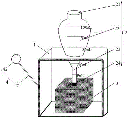
[0010] see figure 1 The above-mentioned magnetic suspension concentration measuring device for accelerating magnetic powder precipitation includes a support 1, a pear-shaped bottle 2, and a magnet 3. Positioning holes are provided on the support 1 for insertion and positioning of the pear-shaped bottle 2, and the magnet 3 is placed on the pear-shaped bottle 2. and contact with the bottom of the pear-shaped bottle 2, the pear-shaped bottle 2 comprises a top opening 21, a bottle body 22, a bottleneck 23, a bottom seal 24, and the diameter of the bottleneck 23 is less than the diameter of the bottle body 22, the bottle body 22 and the bottleneck 23 Mark the scale line on the top, and the diameter of the bottle neck 23 close to the bottom seal 24 is tapered to form an arc-shaped bottom seal 24 .

[0011] The arc-sha...


PUM


Abstract

The invention provides a magnetic suspension solution concentration determination device capable of accelerating magnetic powder precipitation. The magnetic suspension solution concentration determination device comprises a bracket, a pear-shaped bottle and a magnet, wherein a positioning hole is formed in the bracket and is used for inserting and positioning the pear-shaped bottle; the magnet is arranged at the bottom of the pear-shaped bottle and is in contact with the bottom of the pear-shaped bottle; the pear-shaped bottle comprises a top opening, a bottle body, a bottleneck and a bottom sealing opening; the diameter of the bottleneck is smaller than that of the bottle body; scale marked lines are marked on the bottle body and the bottle neck; and the diameter of the bottleneck close to the bottom sealing opening is gradually reduced so that the circular-arc-shaped bottom sealing opening is formed. The magnet is arranged at the bottom of the pear-shaped bottle and the magnetic field intensity of the magnet can be randomly selected; the pear-shaped bottle is arranged in a magnetic field of the magnet, so that magnetic powder can be naturally deposited under the effect of self gravity and the deposition speed is increased under action of the acting force of the magnetic field; and particularly, the acting force on the magnetic powder in the pear-shaped bottle in the bracket by the magnetic field is relatively large, and the deposition speed is very high.

Description

technical field [0001] The invention relates to a magnetic powder concentration detection device used in non-destructive detection technology, in particular to a magnetic suspension liquid concentration measurement device for accelerating magnetic powder precipitation. Background technique [0002] The magnetic powder used in nondestructive testing technology is mainly composed of Fe 2 o 3 , Fe 3 o 4 And Fe and other components, these three substances are all ferromagnetic, the natural precipitation method is often used in the prior art, that is, put the pear-shaped bottle containing the magnetic powder suspension on the support, wait for at least 30 minutes, and wait for the magnetic powder to settle. Read again to calculate its concentration, this method waits for a long time, and labor efficiency is very low. [0003] In the prior art, a coil is also used to surround the outside of the pear-shaped bottle, and then the coil is energized to form a directional magnetic f...

Claims


Application Information

Patent Timeline
IPC IPC(8): G01N27/74
CPCG01N27/74
Inventor 李飞
Owner KOCEL STEEL
Learn More