
Leakage waveguide for rail transport vehicle-ground wireless transmission comprehensive carrying communication system

A leaky waveguide and wireless transmission technology, applied in waveguide, waveguide-type devices, circuits, etc., can solve problems such as not suitable for new system technical requirements, achieve good in-band frequency response, improve radiation performance, and uniform field intensity radiation Effect

Active Publication Date: 2016-07-20
TONGHAO CABLE GRP CO LTD
View PDF6 Cites 10 Cited by
  • Summary
  • Abstract
  • Description
  • Claims
  • Application Information

AI Technical Summary

Problems solved by technology

According to the application experience of foreign 5.9G wireless transmission integrated bearer communication system, the single-directional coverage distance of the system should generally not be less than 400m. In summary, the 1 / 2" radial leakage cable is not suitable for the technical requirements of the new system

Method used


Image

  • Leakage waveguide for rail transport vehicle-ground wireless transmission comprehensive carrying communication system
  • Leakage waveguide for rail transport vehicle-ground wireless transmission comprehensive carrying communication system
  • Leakage waveguide for rail transport vehicle-ground wireless transmission comprehensive carrying communication system

Examples


Embodiment Construction

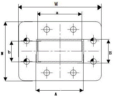
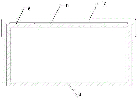
[0037] Such as figure 1 , figure 2 and image 3 As shown, the present invention includes a metal waveguide 1 with a rectangular cross-section. The two ends of the metal waveguide 1 are respectively sealed and welded to a left metal flange 2 and a right metal flange 3. On the central axis of one of the wide sides of the metal waveguide 1 A row of leakage gaps 4 are milled on both sides, and a layer of plastic tape 5 and a layer of flame-retardant adhesive tape 6 are sequentially bonded on the wide side of the metal waveguide 1 provided with leakage gaps 4, and pressed on the outer surface of the flame-retardant adhesive tape. One deck of flame-retardant glass cloth 7 is established; the leakage gap 4 includes the first row of leakage gaps 4-1 and the second row of leakage gaps 4-2, and each row of leakage gaps includes N leakage gaps 4, and each row of leakage gaps 4 are arranged equidistantly at intervals, and each leakage gap 4 includes a horizontal groove 8, and the two e...


PUM

PropertyMeasurementUnit
The inside diameter ofaaaaaaaaaa

Abstract

The invention discloses a leakage waveguide for a rail transport vehicle-ground wireless transmission comprehensive carrying communication system. The leakage waveguide comprises a metal waveguide tube with a rectangular section. A left metal flange and a right metal flange are respectively seal-welded to the two ends of the metal waveguide tube. A row of leakage gaps is milled at each side of the central axis of one wide side face of the metal waveguide tube, the wide side face, provided with the leakage gaps, of the metal waveguide tube is sequentially pasted with a layer of plastic adhesive tape and a layer of flame-retardant rubberized fabric, and a layer of flame-retardant glass fiber cloth is arranged in a pressing manner on the outer surface of the flame-retardant rubberized fabric. When the leakage gaps cut different positions of the wall of the waveguide tube, the shapes and sizes of the leakage gaps differ, and the field intensity of outward radiation of the leakage gaps differs.

Description

technical field [0001] The invention relates to the technical field of rail transit wireless communication, in particular to a leaky waveguide for a rail transit vehicle wireless transmission integrated bearer communication system. Background technique [0002] With the development of urban rail transit wireless communication technology, CBTC signal system has been widely adopted by domestic and foreign urban rail transit signal systems. The frequency of the existing urban rail transit vehicle-to-ground wireless transmission signal system (CBTC) is 2.4GHz to 2.5GHz, and most of the electronic equipment using this frequency band, such as Wifi, iPad, wireless mouse, cordless phone, Bluetooth equipment and medical testing Equipment, etc., and even microwave ovens also use 2.4GHz frequency, which will undoubtedly cause varying degrees of interference to the train-to-ground wireless transmission signal system, thereby also affecting the safe operation of the train. [0003] In o...

Claims


Application Information

Patent Timeline
IPC IPC(8): H01P3/06
CPCH01P3/06
Inventor 王如彬尚爱民王胜军白龙刚许慕军魏腾飞王志辉
Owner TONGHAO CABLE GRP CO LTD
Learn More