
Power supply for achieving pulse microwave output employing magnetron and control method of power supply

A technology of pulsed microwave and magnetron, which is applied in the field of power supply and control of pulsed microwave output by magnetron, can solve the problems that hinder the application process of microwave "thermal effect" and "non-thermal effect, lack of high-power pulsed microwave, etc., and achieve Achieving Precisely Controlled Effects

Active Publication Date: 2016-07-20
NANHUA UNIV
View PDF2 Cites 12 Cited by
  • Summary
  • Abstract
  • Description
  • Claims
  • Application Information

AI Technical Summary

Problems solved by technology

The lack of reasonably priced high-power pulsed microwaves on the market hinders the application process of microwave "thermal effect" and "non-thermal effect" to a certain extent

Method used


Image

  • Power supply for achieving pulse microwave output employing magnetron and control method of power supply
  • Power supply for achieving pulse microwave output employing magnetron and control method of power supply
  • Power supply for achieving pulse microwave output employing magnetron and control method of power supply

Examples


Embodiment 1

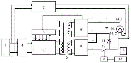
[0028] Example 1: A 2.45GHz magnetron 2M469 is used with a power of 1.05kW, an anode voltage of 4450V, an anode current of 0.25A, a filament voltage of 3.5V, and a current of 10A. The cooling method is water cooling. Using the method proposed by the invention, the negative high voltage between the cathode and the anode is powered by pulse modulation. Such as Figure 5 shown. The mains 220V is connected to the full-bridge inverter circuit composed of 4 FETs after EMI filtering and bridge rectification module. An RCD absorption circuit is connected between the drain and the source of each field effect transistor to reduce switching loss. The midpoint of the bridge arm is connected to the high-frequency step-up transformer through a DC blocking capacitor. The output of the secondary side of the transformer is divided into two windings, in which the main winding passes through 4 fast recovery high-voltage diodes 2CLG7.5K and a high-voltage capacitor to form a rectification and...

Embodiment 2

[0029] Example 2: A 2.45GHz magnetron 2M463G is used with a power of 1.5kW, an anode voltage of 4650V, an anode current of 0.3A, a filament voltage of 3.5V, and a current of 10A. The cooling method is water cooling. Using the method proposed by the invention, the negative high voltage between the cathode and the anode is powered by pulse modulation. The mains 220V is connected to the full-bridge inverter circuit composed of 4 FETs after EMI filtering and bridge rectification module. An RCD absorption circuit is connected between the drain and the source of each field effect transistor to reduce switching loss. The midpoint of the bridge arm is connected to the high-frequency step-up transformer through a DC blocking capacitor. The output of the secondary side of the transformer is divided into two windings, in which the main winding passes through 4 fast recovery high-voltage diodes 2CLG7.5K and a high-voltage capacitor to form a rectification and filtering circuit to obtain...


PUM


Abstract

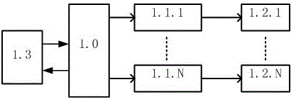
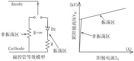
The invention relates to a power supply for achieving pulse microwave output employing a magnetron and a control method of the power supply. The power supply for achieving the pulse microwave output employing the 2.45GHz magnetron comprises a filament power supply, an anode negative high-voltage power supply and a controller. Output of the anode-supply high-voltage power supply of the 2.45GHz magnetron at a certain pulse repetition frequency and a modulated duty ratio is achieved under the condition of not changing heat-sink cooling of the anode, so that accurate and controllable microwave generation time and the maximal output power are achieved; and synthesis of output power multi-tubes of the 2.45GHz magnetron is achieved through control to the requirements of industrial high-power microwave output.

Description

technical field [0001] The invention relates to a power supply device and a control method for a 2.45GHz microwave magnetron to realize the output of pulse microwaves. The conventional 2.45GHz magnetron anode high voltage is changed to a pulse power supply mode, and the output microwave power will be increased by 2~8 times. Not only is it suitable for heating materials in the conventional "thermal effect" method, the temperature can be precisely controlled, but it is also suitable for some occasions where the "non-thermal effect" of using microwaves on the processed object is significant, which can greatly reduce energy consumption. Background technique [0002] With the rapid development of microwave technology, microwave heating is widely used in various industries. Microwave heating has the characteristics of uniform heating, fast heating speed, high efficiency, and keeping the original composition of the processed object unchanged. It gradually replaces the traditional ...

Claims


Application Information

Patent Timeline
IPC IPC(8): H02M11/00H05B6/66
CPCH02M11/00H05B6/664
Inventor 陈文光丁德馨胡南何四军胡波李广悦
Owner NANHUA UNIV
Learn More