Laminate composite wing structures
A composite material and wing technology, applied in the field of systems for strengthening wings, can solve problems such as stringers being easily affected by overturning loads
- Summary
- Abstract
- Description
- Claims
- Application Information
AI Technical Summary
Problems solved by technology
Method used
Image
Examples
example 1
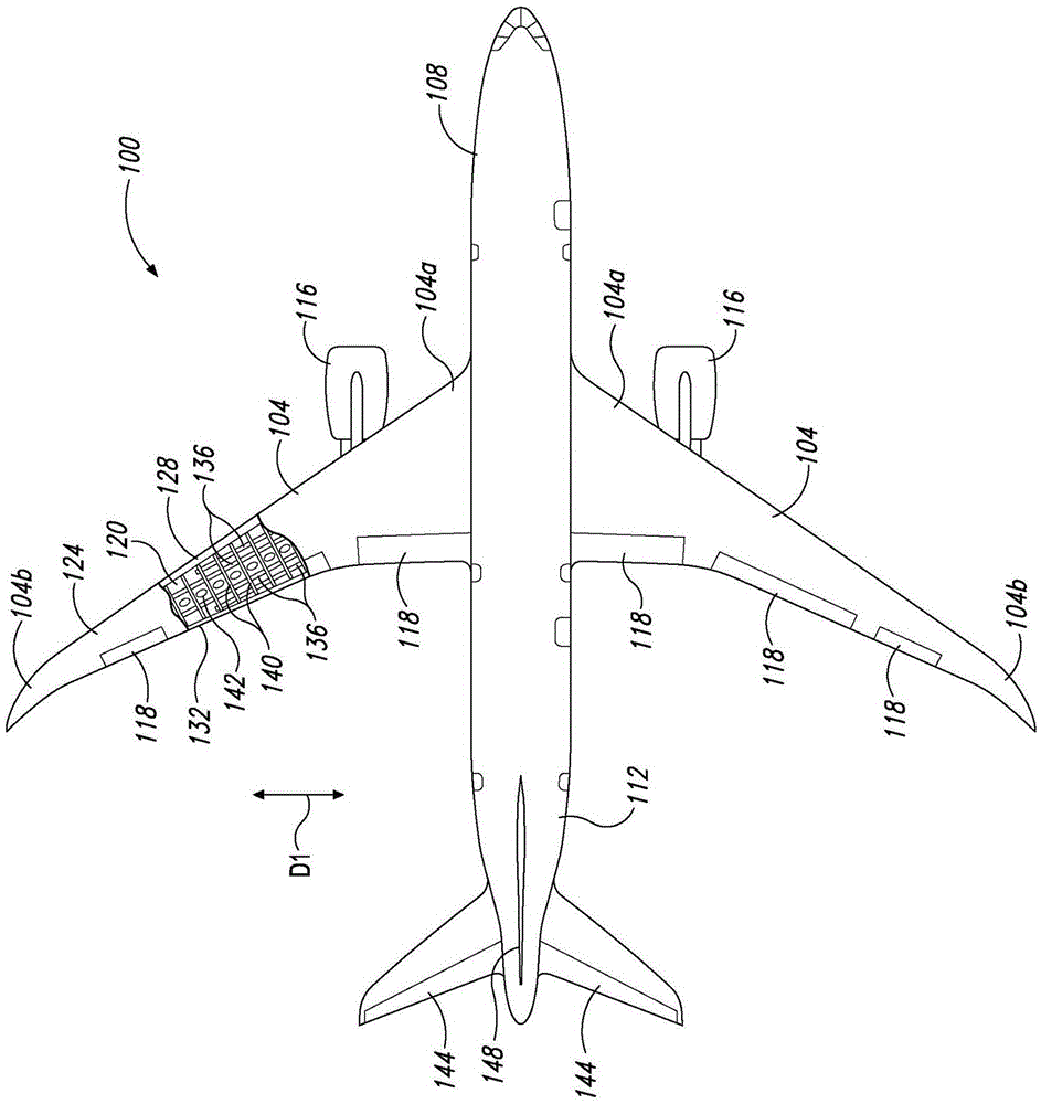
[0045] This example describes an exemplary aircraft 100; see Figure 1 to Figure 7 .
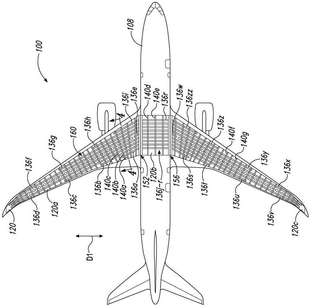
[0046] Such as figure 1 As shown, aircraft 100 may include a pair of wings 104 (eg, in figure 2 with image 3 in the three-piece wing embodiment configuration shown or in Figure 8 to Figure 11 In the illustrated embodiment configuration of a single-piece wing, which will be described in further detail below), a fuselage 108 , a tail 112 and one or more propulsion units 116 .
[0047] Each of the wings 104 may extend outwardly in the fuselage 108 , for example from an inboard portion 104 a to a respective outboard portion 104 b , in a generally parallel spanwise direction D1 of the wing 104 . Wing 104 (or each wing in wing 104) may include control surfaces 118, lower wing skin 120, upper wing skin 124, front spar 128, rear spar 132, a plurality of stringers 136, and a plurality of A wing rib 140.
[0048] Stringers 136 and lower wing skin 120 (in addition to other components of wing 1...
example 2
[0097] This example describes an exemplary single-piece wing implementation that may alternatively be included in aircraft 100; see Figure 8 to Figure 11 .
[0098] In this example, from Figure 8 and Figure 9 As can be seen in , the wing skin 120 may be continuous (or substantially continuous) between the wingtips 104c, 104d of the wing 104 . Further, stringer 136 may include a plurality of stringers (eg, stringers 800a-i), each of which is similar in structure to stringer 136g described above.
[0099] As can be seen, each of the stringers 800a - i may be curved and extend continuously from one wing 104 to the adjacent wing 104 in the aircraft 100 . For example, stringers 800a-i (eg, such as Figure 8 and Figure 11 shown in the direction toward the tail) has one or more sweeping curvatures and (for example, as Figure 9 and Figure 10 shown, in the upward direction) has one or more dihedral curvatures. The one or more relative axes of general curvature may be subs...
example 3
[0106] This example describes how to stabilize a wing; see Figure 12 . Aspects of components described herein can be used in the method steps described below. Where appropriate, reference is made to components and systems previously described which can be used to perform each step. These references are by way of example and are not intended to limit the possible ways of performing any particular step of the method.
[0107] Figure 12 The flowcharts illustrate steps performed in exemplary methods and may not detail complete processes. Specifically, Figure 12 Depicted are a number of steps of a method (shown generally at 1200 in the figure) that may be performed in conjunction with embodiments disclosed in accordance with aspects of the present disclosure. Although in Figure 12 The various steps of method 1200 may be depicted in and described below, but these steps do not necessarily need to be performed in all, and in some cases may be performed in an order different ...
PUM
 Abstract
Description
Claims
Application Information
 - R&D
- Intellectual Property
- Life Sciences
- Materials
- Tech Scout
- Unparalleled Data Quality
- Higher Quality Content
- 60% Fewer Hallucinations
Browse by: Latest US Patents, China's latest patents, Technical Efficacy Thesaurus, Application Domain, Technology Topic, Popular Technical Reports.
© 2025 PatSnap. All rights reserved.Legal|Privacy policy|Modern Slavery Act Transparency Statement|Sitemap|About US| Contact US: help@patsnap.com


