Rapid and efficient filtering whole blood in capillary flow device

a technology of capillary flow and whole blood, which is applied in the direction of filtration separation, separation process, laboratory glassware, etc., can solve the problems of reducing filtration efficiency, affecting the filtering efficiency, and unable to allow samples to bypass the filter, so as to prevent the formation of filtrate or particles

Active Publication Date: 2010-04-15
MICROPOINT BIOSCI
View PDF15 Cites 36 Cited by
  • Summary
  • Abstract
  • Description
  • Claims
  • Application Information

AI Technical Summary

Benefits of technology

[0013]The cartridge can have additional features to influence fluid flows. For example, the filtration chamber can have a bottom surface with v-shaped (in cross section) groves running parallel to the lateral fluid flow path. The cartridge internal surfaces can have recesses that recede from fluid channels providing non-capillary dimensions that stop undesirable flows along surfaces, e.g., that may circumvent the filter materials. In a preferred embodiment, cartridge has a recess in the cover at a position overlying a filter crush line, thus preventing filtrate or particles from moving above the filter system by capillary action and directing filtrate down into the bottom filter.

Problems solved by technology

However, sealing of the filter in the device to achieve effective filtration, and not allow sample to bypass the filter, is a problem with this technology.
The products are bulky in thickness.
Particulate matter which travels around the filter decreases the filtration efficiency, repeatability, and may cause the filter to be unacceptable for certain applications.
The use of these materials to affect sealing has produced variable, and often poor sealing.
Additionally, these sealing methods can result in absorption of variable amounts of the sealing compound into the filter.
Another drawback of prior art filter devices is the short transverse fluid flow path through a filter's depth.
Filters are generally 0.1 mm to 6 mm thick, this short flow path can provide poor separation efficiency.
However, this single filter technology has the disadvantage that the same filter dealing with the gross particulate of the sample also has to handle the final fine filtration.

Method used


Image

  • Rapid and efficient filtering whole blood in capillary flow device
  • Rapid and efficient filtering whole blood in capillary flow device
  • Rapid and efficient filtering whole blood in capillary flow device

Examples


example 1

A Lateral Flow Filter in a Cartridge

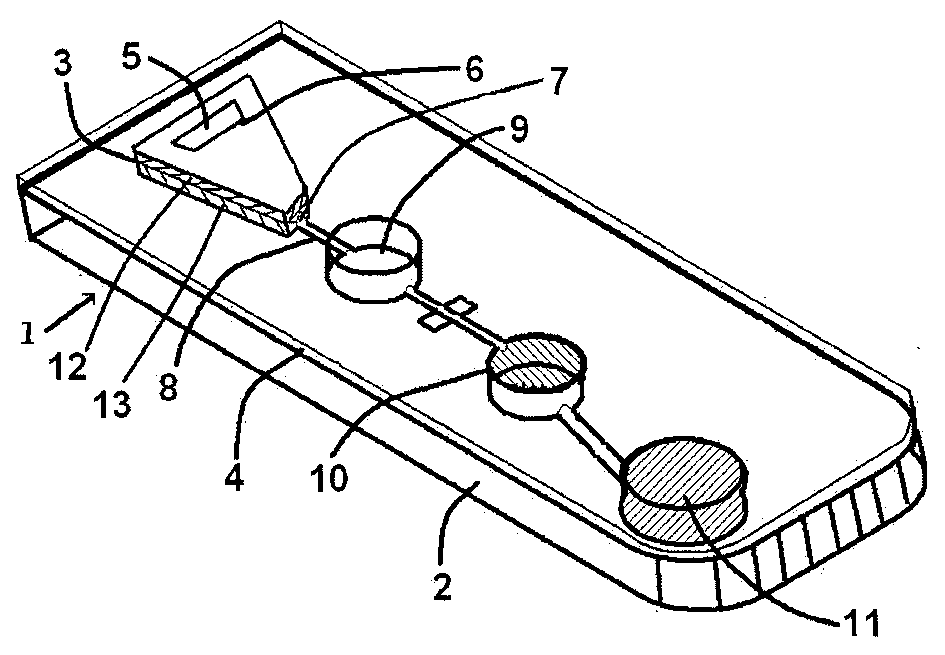
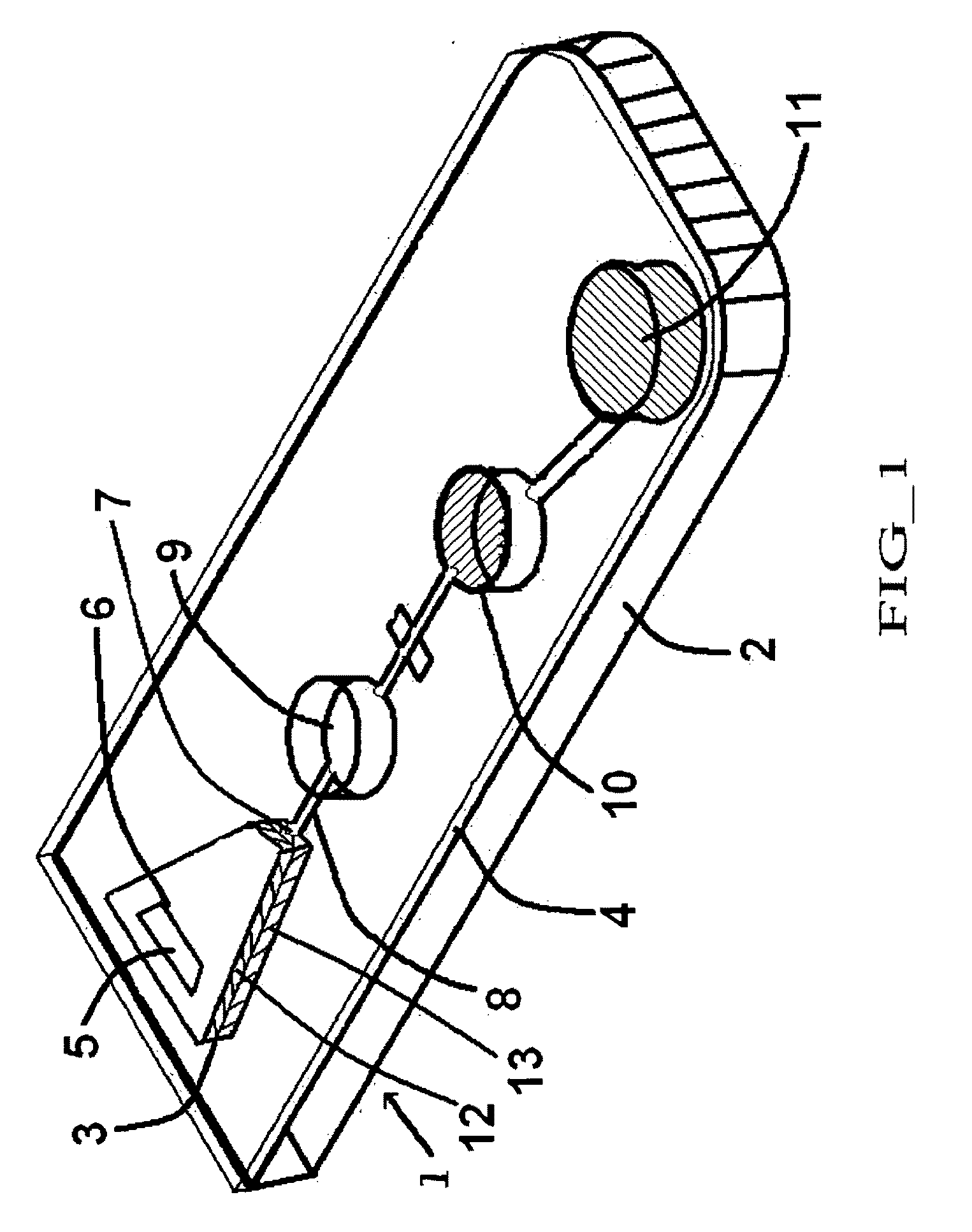
[0043]An assay cartridge is prepared incorporating a lateral flow filter system having a pore size gradient. Such a cartridge can efficiently provide filtered plasma to an assay system with low dead volumes and high flow rates without a requirement for input of external forces.

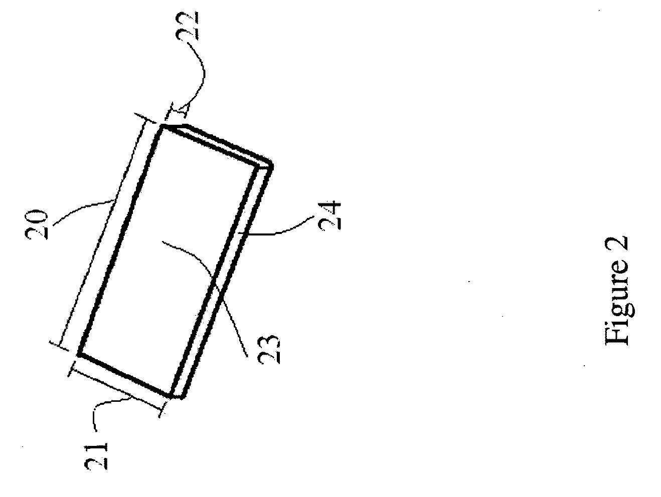
[0044]The cartridge employs two asymmetric gradient filters. A suitable asymmetric filter is Pall BTS-SP-300 GR (see, FIG. 3) or the like, which have a thickness of 300 um. To avoid excessive sample volume requirements, it is not preferred to laminate two or more asymmetric filters with the same pore size to merely increase the filtration path length. Such a configuration can trap whole blood or plasma between filter layers due to the capillary stop effect of a larger pore size along the flow path. For example, to laminate two layers of BTS-SP-300 GR will increase the sample volume and the blood samples will be accumulated in the gap between two layers. However, we have foun...


PUM

PropertyMeasurementUnit
pore sizeaaaaaaaaaa
thickaaaaaaaaaa
diameteraaaaaaaaaa

Abstract

This invention provides lateral flow filters with pore size gradients and with features to prevent peripheral flows around the filter. The filters can be laminated composites of two or more planar filter layers. Cartridges employing the filters can include a filtration chamber configured to retain the lateral flow filters including a port for sample application and a capillary channel for filtrate egress. The fluid egress port can be positioned to receive filtrate from one filter layer but not another.

Description

CROSS-REFERENCE TO RELATED APPLICATIONS[0001]This application claims priority to and benefit of a prior U.S. Provisional Application No. 61 / 007,578, Rapid and Efficient Filtering Whole Blood in a Capillary Flow Device, by Nan Zhang, et al., filed Dec. 12, 2007. The full disclosure of the prior application is incorporated herein by reference.FIELD OF THE INVENTION[0002]The invention is in the field of lateral flow filtration elements and cartridges employing such filter elements to separate particles from sample suspensions. The filters can include a fluid flow along the length of a planar filter to exit as filtrate into a capillary channel. The filters can be two or more filter elements laminated, e.g., with larger pores at the point of sample application than at the region of filtrate egress.BACKGROUND OF THE INVENTION[0003]Diagnostic tests frequently are performed on biological samples, such as whole blood or urine that include substantial amounts of particulate matter that can cl...

Claims


Application Information

Patent Timeline
Patent Type & Authority Applications(United States)
IPC IPC(8): B01D27/00
CPCB01L3/502753B01L2400/0406B01L2300/0681
Inventor ZHANG, NANWAN, ZHILIANGSURANGALIKAR, HARSHAL
Owner MICROPOINT BIOSCI
Why Eureka
Try Eureka